HP ProBook 4535s HP ProBook 4535s Notebook PC - Maintenance and Service Guide - Page 73
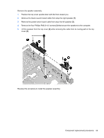
Lift the speaker from the top cover, Remove the speaker assembly
 |
View all HP ProBook 4535s manuals
Add to My Manuals
Save this manual to your list of manuals |
Page 73 highlights
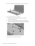
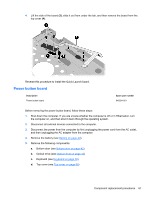
Remove the speaker assembly: 1. Position the top cover upside-down with the front toward you. 2. Remove the Quick Launch board cable from atop the right speaker (1). 3. Remove the power button board cable from atop the left speaker (2). 4. Remove the four Phillips PM2.0×4.0 screws (3) that secure the speakers to the computer. 5. Lift the speaker from the top cover (4) while removing the cable from its routing path in the top cover (5). Reverse this procedure to install the speaker assembly. Component replacement procedures 65
-
 1
1 -
2
-
3
-
4
-
5
-
6
-
7
-
8
-
9
-
10
-
11
-
12
-
13
-
14
-
15
-
16
-
17
-
18
-
19
-
20
-
21
-
22
-
23
-
24
-
25
-
26
-
27
-
28
-
29
-
30
-
31
-
32
-
33
-
34
-
35
-
36
-
37
-
38
-
39
-
40
-
41
-
42
-
43
-
44
-
45
-
46
-
47
-
48
-
49
-
50
-
51
-
52
-
53
-
54
-
55
-
56
-
57
-
58
-
59
-
60
-
61
-
62
-
63
-
64
-
65
-
66
-
67
-
 68
68 -
 69
69 -
 70
70 -
 71
71 -
 72
72 -
 73
73 -
 74
74 -
 75
75 -
 76
76 -
 77
77 -
 78
78 -
79
-
80
-
81
-
82
-
83
-
84
-
85
-
86
-
87
-
88
-
89
-
90
-
91
-
92
-
93
-
94
-
95
-
96
-
97
-
98
-
99
-
100
-
101
-
102
-
103
-
104
-
105
-
106
-
107
-
108
-
109
-
110
-
111
-
112
-
113
-
114
-
115
-
116
-
117
-
118
-
119
-
120
-
121
-
122
-
123
-
124
-
125
-
126
-
127
-
128
-
129
-
130
-
131
-
132
-
133
-
134
-
135
-
136
 |
 |
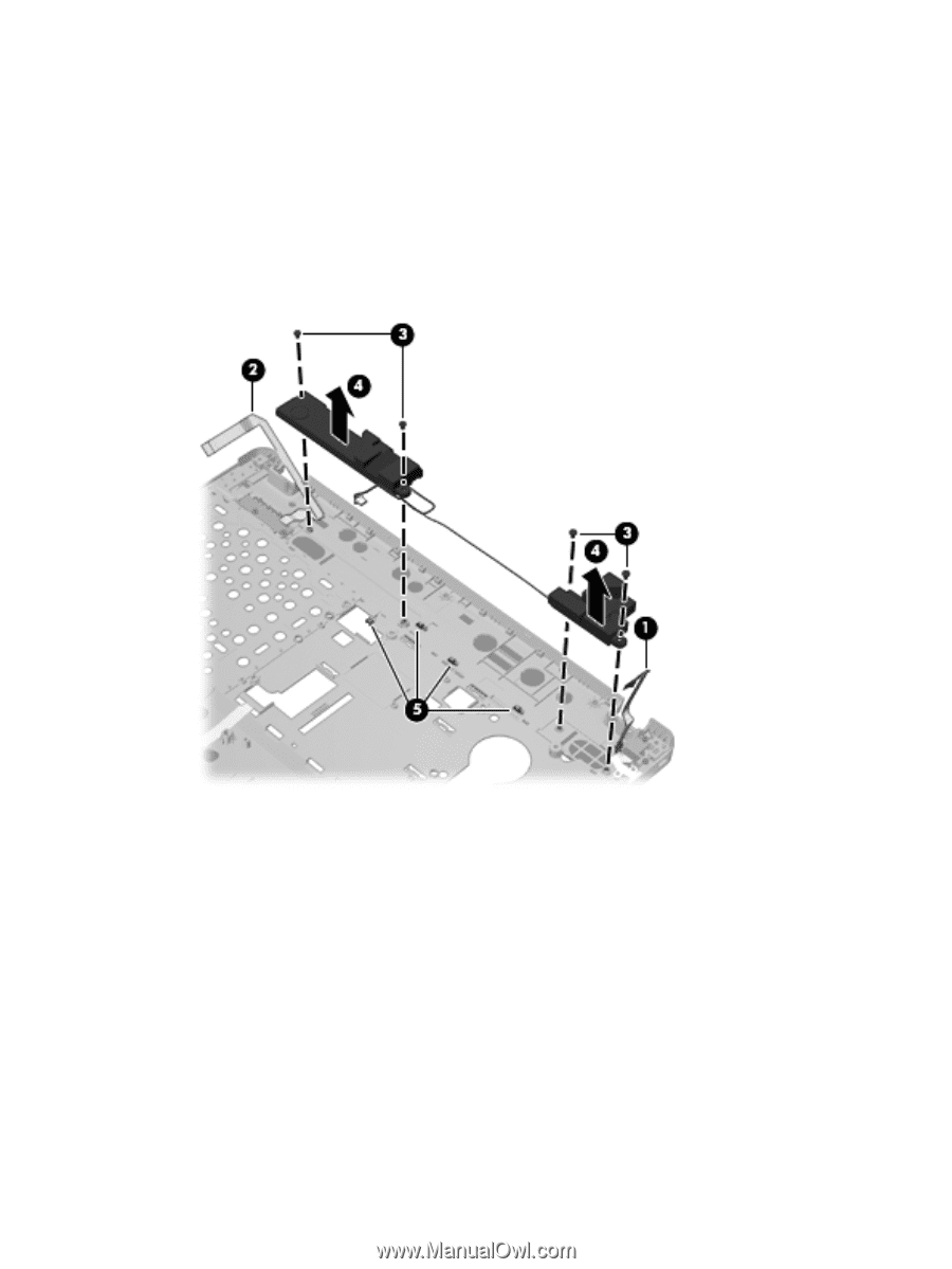
Remove the speaker assembly:
1.
Position the top cover upside-down with the front toward you.
2.
Remove the Quick Launch board cable from atop the right speaker
(1)
.
3.
Remove the power button board cable from atop the left speaker
(2)
.
4.
Remove the four Phillips PM2.0×4.0 screws
(3)
that secure the speakers to the computer.
5.
Lift the speaker from the top cover
(4)
while removing the cable from its routing path in the top
cover
(5)
.
Reverse this procedure to install the speaker assembly.
Component replacement procedures
65