HP Superdome SX2000 User Service Guide, Seventh Edition - HP Integrity Superdo - Page 111
Cell Board Ejectors, Front EMI Panel Flange and Cabinet Holes, If needed
 |
View all HP Superdome SX2000 manuals
Add to My Manuals
Save this manual to your list of manuals |
Page 111 highlights
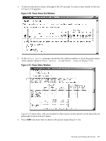
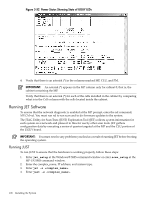
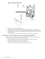
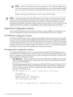
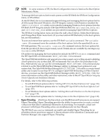
Figure 3-54 Cell Board Ejectors 4. Reinstall the front EMI panel (Figure 3-55). Figure 3-55 Front EMI Panel Flange and Cabinet Holes a. Hook the flange at the lower corners of the EMI panel into the holes on the cabinet. b. Position the panel at the top lip, and lift the panel up while pushing the bottom into position. If needed, compress the EMI gasket to seat the panel properly. c. Reattach the screw at the top of the EMI panel. 5. Check that the cables inside the rear enclosure are secure. Performing a Visual Inspection and Completing the Installation 111
-
 1
1 -
2
-
3
-
4
-
5
-
6
-
7
-
8
-
9
-
10
-
11
-
12
-
13
-
14
-
15
-
16
-
17
-
18
-
19
-
20
-
21
-
22
-
23
-
24
-
25
-
26
-
27
-
28
-
29
-
30
-
31
-
32
-
33
-
34
-
35
-
36
-
37
-
38
-
39
-
40
-
41
-
42
-
43
-
44
-
45
-
46
-
47
-
48
-
49
-
50
-
51
-
52
-
53
-
54
-
55
-
56
-
57
-
58
-
59
-
60
-
61
-
62
-
63
-
64
-
65
-
66
-
67
-
68
-
69
-
70
-
71
-
72
-
73
-
74
-
75
-
76
-
77
-
78
-
79
-
80
-
81
-
82
-
83
-
84
-
85
-
86
-
87
-
88
-
89
-
90
-
91
-
92
-
93
-
94
-
95
-
96
-
97
-
98
-
99
-
100
-
101
-
102
-
103
-
104
-
105
-
 106
106 -
 107
107 -
 108
108 -
 109
109 -
 110
110 -
 111
111 -
 112
112 -
 113
113 -
 114
114 -
 115
115 -
 116
116 -
117
-
118
-
119
-
120
-
121
-
122
-
123
-
124
-
125
-
126
-
127
-
128
-
129
-
130
-
131
-
132
-
133
-
134
-
135
-
136
-
137
-
138
-
139
-
140
-
141
-
142
-
143
-
144
-
145
-
146
-
147
-
148
-
149
-
150
-
151
-
152
-
153
-
154
-
155
-
156
-
157
-
158
-
159
-
160
-
161
-
162
-
163
-
164
-
165
-
166
-
167
-
168
-
169
-
170
-
171
-
172
-
173
-
174
-
175
-
176
-
177
-
178
-
179
-
180
-
181
-
182
-
183
-
184
-
185
-
186
-
187
-
188
-
189
-
190
-
191
-
192
-
193
-
194
-
195
-
196
-
197
-
198
-
199
-
200
 |
 |
Figure 3-54 Cell Board Ejectors
4.
Reinstall the front EMI panel (
Figure 3-55
).
Figure 3-55 Front EMI Panel Flange and Cabinet Holes
a.
Hook the flange at the lower corners of the EMI panel into the holes on the cabinet.
b.
Position the panel at the top lip, and lift the panel up while pushing the bottom into
position.
If needed, compress the EMI gasket to seat the panel properly.
c.
Reattach the screw at the top of the EMI panel.
5.
Check that the cables inside the rear enclosure are secure.
Performing a Visual Inspection and Completing the Installation
111