HP Superdome SX2000 User Service Guide, Seventh Edition - HP Integrity Superdo - Page 30
CPUs and Memories, Backplane Power Supply Module, Backplane Rear View
 |
View all HP Superdome SX2000 manuals
Add to My Manuals
Save this manual to your list of manuals |
Page 30 highlights
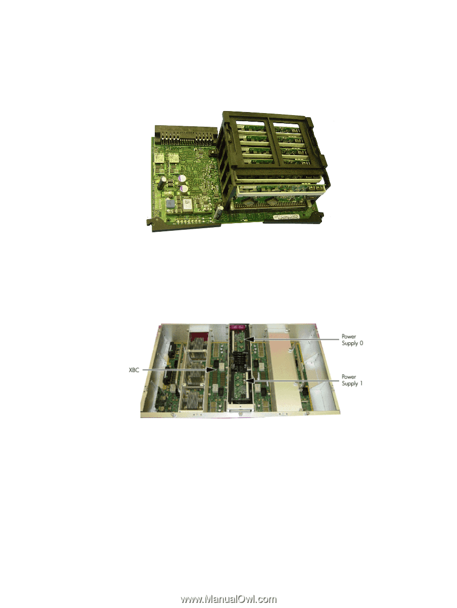
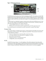
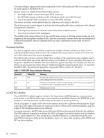
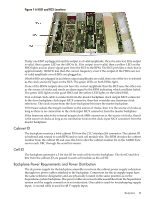
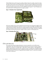
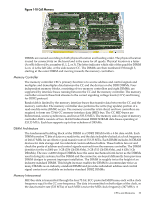
The backplane has two slots for power supply modules. The power supply connector for each slot has a 1-bit slot address to identify the slot. The address bit for power supply slot 0 is grounded. The address bit for slot 1 floats on the backplane. The power supply module provides a pull-up resistor on the address line on slot 1. The power supply module uses the slot address bit as bit A0 for generating a unique I2C address for the FRU ID prom. Figures 1-7 and 1-8 identify and show the location of the backplane power supply modules. Figure 1-7 Backplane Power Supply Module Each power supply slot has a power supply detect bit that determines if the power supply module is inserted into the backplane slot. This bit is routed to an input on the RPMs. The RPM provides a pull-up resistor for logic 1 when the power supply module is missing. When the power supply module is inserted into the slot, the bit is grounded by the power supply and logic 0 is detected by the RPM, indicating that the power supply module is present in the backplane slot. Figure 1-8 Backplane (Rear View) CPUs and Memories The cell provides the processing and memory resources required by each sx2000 system configuration. Each cell includes the following components: four processor module sockets, a single cell (or coherency) controller ASIC, a high-speed crossbar interface, a high-speed I/O interface, eight memory controller ASICs, capacity for up to 32 double-data rate (DDR) DIMMs, high-speed clock distribution circuitry, a management subsystem interface, scan (JTAG) circuitry for manufacturing test, and a low-voltage DC power interface. Figure 1-9 shows the locations of the major components. 30 Overview
-
 1
1 -
2
-
3
-
4
-
5
-
6
-
7
-
8
-
9
-
10
-
11
-
12
-
13
-
14
-
15
-
16
-
17
-
18
-
19
-
20
-
21
-
22
-
23
-
24
-
 25
25 -
 26
26 -
 27
27 -
 28
28 -
 29
29 -
 30
30 -
 31
31 -
 32
32 -
 33
33 -
 34
34 -
 35
35 -
36
-
37
-
38
-
39
-
40
-
41
-
42
-
43
-
44
-
45
-
46
-
47
-
48
-
49
-
50
-
51
-
52
-
53
-
54
-
55
-
56
-
57
-
58
-
59
-
60
-
61
-
62
-
63
-
64
-
65
-
66
-
67
-
68
-
69
-
70
-
71
-
72
-
73
-
74
-
75
-
76
-
77
-
78
-
79
-
80
-
81
-
82
-
83
-
84
-
85
-
86
-
87
-
88
-
89
-
90
-
91
-
92
-
93
-
94
-
95
-
96
-
97
-
98
-
99
-
100
-
101
-
102
-
103
-
104
-
105
-
106
-
107
-
108
-
109
-
110
-
111
-
112
-
113
-
114
-
115
-
116
-
117
-
118
-
119
-
120
-
121
-
122
-
123
-
124
-
125
-
126
-
127
-
128
-
129
-
130
-
131
-
132
-
133
-
134
-
135
-
136
-
137
-
138
-
139
-
140
-
141
-
142
-
143
-
144
-
145
-
146
-
147
-
148
-
149
-
150
-
151
-
152
-
153
-
154
-
155
-
156
-
157
-
158
-
159
-
160
-
161
-
162
-
163
-
164
-
165
-
166
-
167
-
168
-
169
-
170
-
171
-
172
-
173
-
174
-
175
-
176
-
177
-
178
-
179
-
180
-
181
-
182
-
183
-
184
-
185
-
186
-
187
-
188
-
189
-
190
-
191
-
192
-
193
-
194
-
195
-
196
-
197
-
198
-
199
-
200
 |
 |