HP Superdome SX2000 User Service Guide, Seventh Edition - HP Integrity Superdo - Page 38
PCI-X Backplane Functionality, SBA Chip CC-to-Ropes
 |
View all HP Superdome SX2000 manuals
Add to My Manuals
Save this manual to your list of manuals |
Page 38 highlights
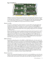
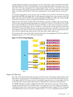
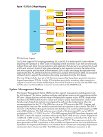
A new concept for the sx2000 is a fat rope. A fat rope is logically one rope that has 32 wires. It consists of two single ropes but has the four command wires in the second single rope removed. The concept of a single rope remains unchanged. It has 18 signals, of which 10 are bidirectional, single-ended address and data bits. Two pairs of unidirectional, single-ended lines carry commands in each direction and a differential strobe pair for each direction. These are all enhanced ropes, which support double the bandwidth of plain ropes and additional protocol behavior. Ropes transfer source-synchronous data on both edges of the clock and can run at either of two speeds. The major components in the I/O chassis are the system bus adapter (SBA) ASIC and 12 logical bus adapter (LBA) ASICs. The high speed serial (HSS) links (one inbound and one outbound) are a group of 20 high-speed serial differential connections using a cable that enables the I/O chassis to be located as much as 14 feet away from the cell board. This enables the use of an I/O expansion cabinet to provide more I/O slots than fit in the main system cabinet. Enhanced ropes are fast, narrow links that connect singly or in pairs between the SBA and four specific LBAs. Fat ropes are enhanced dual-width ropes that are treated logically as a single rope. A fat rope can connect to an LBA. Dual fat ropes can connect to an LBA. A PCI-X I/O chassis consist of four printed circuit assemblies (the PCI-X I/O backplane, the PCI-X I/O power board, the PCI-X I/O power transfer board, and the doorbell board) plus the necessary mechanical components required to support 12 PCI card slots. The master I/O backplane (HMIOB) provides easy connectivity for the I/O chassis. The HSS link and utilities signals come through the master I/O backplane. Most of the utilities signals travel between the UGUY and the I/O backplane, with a few passing through to the I/O power board. The I/O power board contains all the power converters that produce the various voltages needed on the I/O backplane. Both the I/O backplane and the I/O power board have FRU EEPROMs. An I/O power transfer board provides the electrical connections for power and utility signals between the I/O backplane and I/O power board. PCI-X Backplane Functionality The majority of the functionality of a PCI-X I/O backplane is provided by a single SBA ASIC and twelve LBA ASICs (one per PCI slot). A dual-slot hot-plug controller chip plus related logic is also associated with each pair of PCI slots. The SBA is the primary I/O component. Upstream, the SBA communicates directly with the cell controller CC ASIC of the host cell board through a high-bandwidth logical connection (HSS link). Downstream, the SBA spawns 16 logical ropes that communicate with the LBA PCI interface chips. Each PCI chip produces a single 64-bit PCI-X bus supporting a single PCI or PCI-X add-in card. The SBA and the CC are components of the sx2000 and are not compatible with the legacy or Integrity CECs. The newer design for the LBA PCI chip replaces the previous design for LBA chip providing PCI-X 2.0 features. Link signals are routed directly from one of the system connector groups to the SBA. The 16 ropes generated by the SBA are routed to the LBA chips as follows: • The four LBAs are tied to the SBA by single-rope connections and are capable of peak data rates of 533 MB/s (equivalent to the peak bandwidth of PCI 4x or PCIX-66). • LBAs are tied to the SBA by either a single fat or dual-rope connections and are capable of peak data rates of 1.06 GB/s (equivalent to the peak bandwidth of PCIX-133). Two LBAs use dual-fat rope connections and are capable of peak data rates of 2.12 GB/s (equivalent to the peak bandwidth of PCIX-266). Internally, the SBA is divided into two halves, each supporting four single ropes and four fat ropes. The I/O backplane routing interconnects the ASICs in order to balance the I/O load on each half of the SBA. SBA Chip CC-to-Ropes The SBA chip communicates with the CC on the cell board through a pair of high-speed serial unidirectional links (HSS or e-Links). Each unidirectional e-Link consists of 20 serial 8b/10b 38 Overview
-
 1
1 -
2
-
3
-
4
-
5
-
6
-
7
-
8
-
9
-
10
-
11
-
12
-
13
-
14
-
15
-
16
-
17
-
18
-
19
-
20
-
21
-
22
-
23
-
24
-
25
-
26
-
27
-
28
-
29
-
30
-
31
-
32
-
 33
33 -
 34
34 -
 35
35 -
 36
36 -
 37
37 -
 38
38 -
 39
39 -
 40
40 -
 41
41 -
 42
42 -
 43
43 -
44
-
45
-
46
-
47
-
48
-
49
-
50
-
51
-
52
-
53
-
54
-
55
-
56
-
57
-
58
-
59
-
60
-
61
-
62
-
63
-
64
-
65
-
66
-
67
-
68
-
69
-
70
-
71
-
72
-
73
-
74
-
75
-
76
-
77
-
78
-
79
-
80
-
81
-
82
-
83
-
84
-
85
-
86
-
87
-
88
-
89
-
90
-
91
-
92
-
93
-
94
-
95
-
96
-
97
-
98
-
99
-
100
-
101
-
102
-
103
-
104
-
105
-
106
-
107
-
108
-
109
-
110
-
111
-
112
-
113
-
114
-
115
-
116
-
117
-
118
-
119
-
120
-
121
-
122
-
123
-
124
-
125
-
126
-
127
-
128
-
129
-
130
-
131
-
132
-
133
-
134
-
135
-
136
-
137
-
138
-
139
-
140
-
141
-
142
-
143
-
144
-
145
-
146
-
147
-
148
-
149
-
150
-
151
-
152
-
153
-
154
-
155
-
156
-
157
-
158
-
159
-
160
-
161
-
162
-
163
-
164
-
165
-
166
-
167
-
168
-
169
-
170
-
171
-
172
-
173
-
174
-
175
-
176
-
177
-
178
-
179
-
180
-
181
-
182
-
183
-
184
-
185
-
186
-
187
-
188
-
189
-
190
-
191
-
192
-
193
-
194
-
195
-
196
-
197
-
198
-
199
-
200
 |
 |