HP Surestore Disk Array 12h HP SureStore E Disk Array 12H User's and Service M - Page 243
Rack Array/Component Positioning for a visual, Table 21,
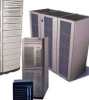 |
View all HP Surestore Disk Array 12h manuals
Add to My Manuals
Save this manual to your list of manuals |
Page 243 highlights
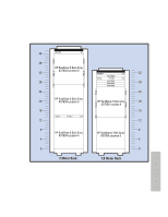
Appendix D. Back-to-Back Racking Installation Procedure 2. Take disk arrays offline, power down rack and remove existing components Of the items that are removed, some are removed to be replace by new components. Some may need to be removed, such as the disk array enclosures to allow the enclosure rails to be repositioned (since back-to-back racking in the 2-meter rack utilizes all EIA units, including the bottom unit). For additional clarification, refer to the detailed installation steps following this step. a) Unmount all file systems associated with the devices in the rack. b) Bring devices in the rack offline. c) Power down the devices in the rack. d) Unplug the rack's PDU cables from the power source. e) Remove the rack's rear door and side panels. f) Remove the rear door, hinges, and latch catch. (These will not be used again) g) Remove the PDUs (56 inch) and brackets from the rack. (These will be replaced with new PDUs) . h) If necessary, remove disk array enclosures (see step 4 below). The disk array enclosures are heavy. Prior to removing the enclosure, the individual disk modules should be removed. Also, when reinstalling the disk modules, they should be installed back into the same enclosure from which they were removed (but not necessarily the same slot). Thus, when removing the disk modules, identify on the module from which array enclosure it was removed. i) Remove the top cap from the rack. j) Remove any fans (these will be replace by high-volume exhaust fans). 3. Install the exhaust fan assembly Install this assembly as described in the Exhaust Fan Assembly Installation Guide (E7687-90001) 4 Install rail kits and/or reposition rails as needed Install new rail kits as needed to hold the number of disk enclosures to be racked. Ensure that the rails are installed as indicated in Table 21 for either the 1.6-meter or the 2-meter rack. (Rail installation is described in Appendix C of this document.) Refer to Figure 50 Rack Array/Component Positioning for a visual representation of the placement of the arrays/components. Also, install the clip nuts for the array enclosure flange as indicated in Table 21. Remember, if the rack has side access, you can install disk enclosures in the high-density configuration; if side access is not an option, one enclosure space must remain vacant, see Figure 49. 243 Racking
-
 1
1 -
2
-
3
-
4
-
5
-
6
-
7
-
8
-
9
-
10
-
11
-
12
-
13
-
14
-
15
-
16
-
17
-
18
-
19
-
20
-
21
-
22
-
23
-
24
-
25
-
26
-
27
-
28
-
29
-
30
-
31
-
32
-
33
-
34
-
35
-
36
-
37
-
38
-
39
-
40
-
41
-
42
-
43
-
44
-
45
-
46
-
47
-
48
-
49
-
50
-
51
-
52
-
53
-
54
-
55
-
56
-
57
-
58
-
59
-
60
-
61
-
62
-
63
-
64
-
65
-
66
-
67
-
68
-
69
-
70
-
71
-
72
-
73
-
74
-
75
-
76
-
77
-
78
-
79
-
80
-
81
-
82
-
83
-
84
-
85
-
86
-
87
-
88
-
89
-
90
-
91
-
92
-
93
-
94
-
95
-
96
-
97
-
98
-
99
-
100
-
101
-
102
-
103
-
104
-
105
-
106
-
107
-
108
-
109
-
110
-
111
-
112
-
113
-
114
-
115
-
116
-
117
-
118
-
119
-
120
-
121
-
122
-
123
-
124
-
125
-
126
-
127
-
128
-
129
-
130
-
131
-
132
-
133
-
134
-
135
-
136
-
137
-
138
-
139
-
140
-
141
-
142
-
143
-
144
-
145
-
146
-
147
-
148
-
149
-
150
-
151
-
152
-
153
-
154
-
155
-
156
-
157
-
158
-
159
-
160
-
161
-
162
-
163
-
164
-
165
-
166
-
167
-
168
-
169
-
170
-
171
-
172
-
173
-
174
-
175
-
176
-
177
-
178
-
179
-
180
-
181
-
182
-
183
-
184
-
185
-
186
-
187
-
188
-
189
-
190
-
191
-
192
-
193
-
194
-
195
-
196
-
197
-
198
-
199
-
200
-
201
-
202
-
203
-
204
-
205
-
206
-
207
-
208
-
209
-
210
-
211
-
212
-
213
-
214
-
215
-
216
-
217
-
218
-
219
-
220
-
221
-
222
-
223
-
224
-
225
-
226
-
227
-
228
-
229
-
230
-
231
-
232
-
233
-
234
-
235
-
236
-
237
-
 238
238 -
 239
239 -
 240
240 -
 241
241 -
 242
242 -
 243
243 -
 244
244 -
 245
245 -
 246
246 -
 247
247 -
 248
248 -
249
-
250
-
251
-
252
-
253
-
254
-
255
-
256
-
257
-
258
-
259
-
260
-
261
-
262
-
263
-
264
-
265
-
266
-
267
-
268
-
269
-
270
-
271
-
272
-
273
-
274
-
275
-
276
 |
 |
