HP TC1100 HP Compaq tc1100 Tablet PC - Maintenance and Service Guide - Page 93
Disassembly Sequence Chart, Table 5-1 - digitizer pen
 |
View all HP TC1100 manuals
Add to My Manuals
Save this manual to your list of manuals |
Page 93 highlights
Removal and Replacement Procedures 5.2 Disassembly Sequence Chart Use the following table to determine the section number to be referenced when removing tablet PC components. Section 5.3 5.4 5.5 5.6 5.7 5.8 5.9 Table 5-1 Disassembly Sequence Chart Description Preparing the tablet PC for disassembly SD Card and PC Card Digitizer pen Battery pack Memory module and PCI device Real time clock (RTC) battery Hard drive Display panel assembly Bridge battery Digitizer System board Bluetooth module Main memory Modem board Fan and heat sink Docking station Number of screws removed 0 0 1 2 0 2 8 0 5 8 0 0 0 3 17 Maintenance and Service Guide 5-3
-
 1
1 -
2
-
3
-
4
-
5
-
6
-
7
-
8
-
9
-
10
-
11
-
12
-
13
-
14
-
15
-
16
-
17
-
18
-
19
-
20
-
21
-
22
-
23
-
24
-
25
-
26
-
27
-
28
-
29
-
30
-
31
-
32
-
33
-
34
-
35
-
36
-
37
-
38
-
39
-
40
-
41
-
42
-
43
-
44
-
45
-
46
-
47
-
48
-
49
-
50
-
51
-
52
-
53
-
54
-
55
-
56
-
57
-
58
-
59
-
60
-
61
-
62
-
63
-
64
-
65
-
66
-
67
-
68
-
69
-
70
-
71
-
72
-
73
-
74
-
75
-
76
-
77
-
78
-
79
-
80
-
81
-
82
-
83
-
84
-
85
-
86
-
87
-
 88
88 -
 89
89 -
 90
90 -
 91
91 -
 92
92 -
 93
93 -
 94
94 -
 95
95 -
 96
96 -
 97
97 -
 98
98 -
99
-
100
-
101
-
102
-
103
-
104
-
105
-
106
-
107
-
108
-
109
-
110
-
111
-
112
-
113
-
114
-
115
-
116
-
117
-
118
-
119
-
120
-
121
-
122
-
123
-
124
-
125
-
126
-
127
-
128
-
129
-
130
-
131
-
132
-
133
-
134
-
135
-
136
-
137
-
138
-
139
-
140
-
141
-
142
-
143
-
144
-
145
-
146
-
147
-
148
-
149
-
150
-
151
-
152
-
153
-
154
-
155
-
156
-
157
-
158
-
159
-
160
-
161
-
162
-
163
-
164
-
165
-
166
-
167
-
168
-
169
-
170
-
171
-
172
-
173
-
174
-
175
-
176
-
177
-
178
-
179
-
180
-
181
-
182
-
183
-
184
-
185
-
186
-
187
-
188
-
189
-
190
-
191
-
192
-
193
 |
 |
Removal and Replacement Procedures
Maintenance and Service Guide
5–3
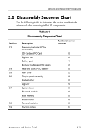
5.2
Disassembly Sequence Chart
Use the following table to determine the section number to be
referenced when removing tablet PC components.
Table 5-1
Disassembly Sequence Chart
Section
Description
Number of screws
removed
5.3
Preparing the tablet PC for
disassembly
SD Card and PC Card
0
Digitizer pen
0
Battery pack
1
Memory module and PCI device
2
5.4
Real time clock (RTC) battery
0
5.5
Hard drive
2
5.6
Display panel assembly
8
Bridge battery
0
Digitizer
5
5.7
System board
8
Bluetooth module
0
Main memory
0
Modem board
0
5.8
Fan and heat sink
3
5.9
Docking station
17