HP Xw6200 HP Workstation xw6200 Service and Technical Reference Guide (3rd Edi - Page 155
SATA Devices, SATA Guidelines
 |
UPC - 882780333536
View all HP Xw6200 manuals
Add to My Manuals
Save this manual to your list of manuals |
Page 155 highlights
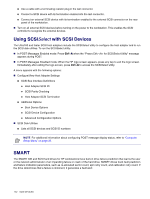
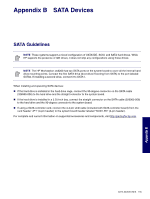
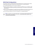
Appendix B SATA Devices SATA Guidelines NOTE These systems support a mixed configuration of UATA/IDE, SCSI, and SATA hard drives. While HP supports the presence of IDE drives, it does not ship any configurations using those drives. NOTE The HP Workstation xw6200 has two SATA ports on the system board to cover all the internal hard drive mounting points. Connect the first SATA drive (boot drive if booting from SATA) to the port labeled SATA0. If installing a second drive, connect it to SATA1. When installing and operating SATA devices: „ If the hard drive is installed in the hard drive cage, connect the 90-degree connector on the SATA cable (326965-006) to the hard drive and the straight connector to the system board. „ If the hard drive is installed in a 5.25-inch bay, connect the straight connector on the SATA cable (326965-006) to the hard drive and the 90-degree connector to the system board. „ If using a SATA controller card, connect the 4-4 pin LED cable (included with SATA controller board) from the card header "JP1" (4-pin header) to the system board header labeled "SCSI LED" (4-pin header). For complete and current information on supported accessories and components, visit http://partsurfer.hp.com. SATA GUIDELINES 155 Appendix B
-
 1
1 -
2
-
3
-
4
-
5
-
6
-
7
-
8
-
9
-
10
-
11
-
12
-
13
-
14
-
15
-
16
-
17
-
18
-
19
-
20
-
21
-
22
-
23
-
24
-
25
-
26
-
27
-
28
-
29
-
30
-
31
-
32
-
33
-
34
-
35
-
36
-
37
-
38
-
39
-
40
-
41
-
42
-
43
-
44
-
45
-
46
-
47
-
48
-
49
-
50
-
51
-
52
-
53
-
54
-
55
-
56
-
57
-
58
-
59
-
60
-
61
-
62
-
63
-
64
-
65
-
66
-
67
-
68
-
69
-
70
-
71
-
72
-
73
-
74
-
75
-
76
-
77
-
78
-
79
-
80
-
81
-
82
-
83
-
84
-
85
-
86
-
87
-
88
-
89
-
90
-
91
-
92
-
93
-
94
-
95
-
96
-
97
-
98
-
99
-
100
-
101
-
102
-
103
-
104
-
105
-
106
-
107
-
108
-
109
-
110
-
111
-
112
-
113
-
114
-
115
-
116
-
117
-
118
-
119
-
120
-
121
-
122
-
123
-
124
-
125
-
126
-
127
-
128
-
129
-
130
-
131
-
132
-
133
-
134
-
135
-
136
-
137
-
138
-
139
-
140
-
141
-
142
-
143
-
144
-
145
-
146
-
147
-
148
-
149
-
 150
150 -
 151
151 -
 152
152 -
 153
153 -
 154
154 -
 155
155 -
 156
156 -
 157
157 -
 158
158 -
 159
159 -
 160
160 -
161
-
162
-
163
-
164
-
165
-
166
-
167
-
168
-
169
-
170
-
171
-
172
-
173
-
174
-
175
-
176
-
177
-
178
-
179
-
180
-
181
-
182
-
183
-
184
-
185
-
186
-
187
-
188
-
189
-
190
-
191
-
192
-
193
-
194
-
195
-
196
-
197
-
198
-
199
-
200
-
201
-
202
-
203
-
204
-
205
-
206
-
207
-
208
-
209
 |
 |