HP Xw6200 HP Workstation xw6200 Service and Technical Reference Guide (3rd Edi - Page 69
System Board Components, Table 4-3
 |
UPC - 882780333536
View all HP Xw6200 manuals
Add to My Manuals
Save this manual to your list of manuals |
Page 69 highlights
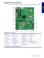
Chapter 4 System Board Components The following image shows the system board connectors and sockets on the HP Workstation xw6200. 1 23 4 5 67 35 34 33 32 31 8 30 29 9 28 27 10 11 12 26 13 14 15 25 24 23 22 21 20 19 18 17 16 Table 4-3 System Board Components 1 MultiBay 10 Battery 19 Serial ATA 2 Memory module pairs 11 Clear CMOS button 20 Serial ATA (primary) 3 Auxiliary power 12 Secondary IDE* 21 Trusted Platform Module 4 Main power 13 Diskette drive 22 Front audio 5 Processor power 14 Primary IDE** 23 Auxiliary audio 6 Processor 1 15 Password header 24 CD-ROM audio 7 Processor 2 16 Front chassis fan 25 PCI Express x8 prime 8 Processor 1 fan 17 Front control panel 26 PCI 9 Processor 2 fan 18 Front USB 27 PCI Express x 16 (graphics) *The Secondary IDE connector is generally used for optical drives. **The Primary IDE connector is generally used for hard drives 28 Rear chassis fans 29 Audio 30 USB/network 31 USB 32 Serial 33 Parallel 34 PS2 Keyboard/mouse 35 Hood lock (Smart Cover lock) SYSTEM BOARD COMPONENTS 69
-
 1
1 -
2
-
3
-
4
-
5
-
6
-
7
-
8
-
9
-
10
-
11
-
12
-
13
-
14
-
15
-
16
-
17
-
18
-
19
-
20
-
21
-
22
-
23
-
24
-
25
-
26
-
27
-
28
-
29
-
30
-
31
-
32
-
33
-
34
-
35
-
36
-
37
-
38
-
39
-
40
-
41
-
42
-
43
-
44
-
45
-
46
-
47
-
48
-
49
-
50
-
51
-
52
-
53
-
54
-
55
-
56
-
57
-
58
-
59
-
60
-
61
-
62
-
63
-
 64
64 -
 65
65 -
 66
66 -
 67
67 -
 68
68 -
 69
69 -
 70
70 -
 71
71 -
 72
72 -
 73
73 -
 74
74 -
75
-
76
-
77
-
78
-
79
-
80
-
81
-
82
-
83
-
84
-
85
-
86
-
87
-
88
-
89
-
90
-
91
-
92
-
93
-
94
-
95
-
96
-
97
-
98
-
99
-
100
-
101
-
102
-
103
-
104
-
105
-
106
-
107
-
108
-
109
-
110
-
111
-
112
-
113
-
114
-
115
-
116
-
117
-
118
-
119
-
120
-
121
-
122
-
123
-
124
-
125
-
126
-
127
-
128
-
129
-
130
-
131
-
132
-
133
-
134
-
135
-
136
-
137
-
138
-
139
-
140
-
141
-
142
-
143
-
144
-
145
-
146
-
147
-
148
-
149
-
150
-
151
-
152
-
153
-
154
-
155
-
156
-
157
-
158
-
159
-
160
-
161
-
162
-
163
-
164
-
165
-
166
-
167
-
168
-
169
-
170
-
171
-
172
-
173
-
174
-
175
-
176
-
177
-
178
-
179
-
180
-
181
-
182
-
183
-
184
-
185
-
186
-
187
-
188
-
189
-
190
-
191
-
192
-
193
-
194
-
195
-
196
-
197
-
198
-
199
-
200
-
201
-
202
-
203
-
204
-
205
-
206
-
207
-
208
-
209
 |
 |
