HP Xw6200 HP Workstation xw6200 Service and Technical Reference Guide (3rd Edi - Page 81
Power Supply
 |
UPC - 882780333536
View all HP Xw6200 manuals
Add to My Manuals
Save this manual to your list of manuals |
Page 81 highlights
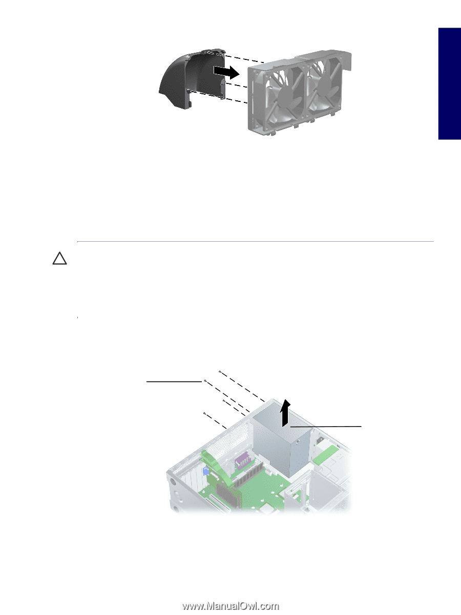
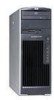
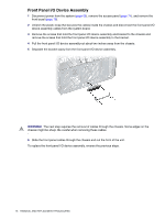
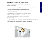
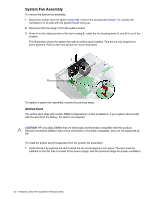
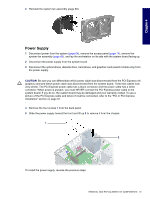
Chapter 4 2 Reinstall the system fan assembly (page 80). Power Supply 1 Disconnect power from the system (page 68), remove the access panel (page 74), remove the system fan assembly (page 80), and lay the workstation on its side with the system board facing up. 2 Disconnect the power supply from the system board. 3 Disconnect the optical drives, diskette drive, hard drives, and graphics card (select models only) from the power supply. CAUTION Be sure you can differentiate which power cable was disconnected from the PCI Express x16 graphics card and which power cable was disconnected from the system board. These two cables look very similar. The PCI Express power cable has a black connector and the power cable has a white connector. When power is present, you must NEVER connect the PCI Express power cable to the system board. If you do so, the system board may be damaged and your warranty voided. To see a picture of the PCI Express cable and where it must be connected, refer to the "PCI or PCI Express Installation" section on page 91. 4 Remove the four screws 1 from the back panel. 5 Slide the power supply toward the front and lift up 2 to remove it from the chassis. 1 2 To install the power supply, reverse the previous steps. REMOVAL AND REPLACEMENT OF COMPONENTS 81
-
 1
1 -
2
-
3
-
4
-
5
-
6
-
7
-
8
-
9
-
10
-
11
-
12
-
13
-
14
-
15
-
16
-
17
-
18
-
19
-
20
-
21
-
22
-
23
-
24
-
25
-
26
-
27
-
28
-
29
-
30
-
31
-
32
-
33
-
34
-
35
-
36
-
37
-
38
-
39
-
40
-
41
-
42
-
43
-
44
-
45
-
46
-
47
-
48
-
49
-
50
-
51
-
52
-
53
-
54
-
55
-
56
-
57
-
58
-
59
-
60
-
61
-
62
-
63
-
64
-
65
-
66
-
67
-
68
-
69
-
70
-
71
-
72
-
73
-
74
-
75
-
 76
76 -
 77
77 -
 78
78 -
 79
79 -
 80
80 -
 81
81 -
 82
82 -
 83
83 -
 84
84 -
 85
85 -
 86
86 -
87
-
88
-
89
-
90
-
91
-
92
-
93
-
94
-
95
-
96
-
97
-
98
-
99
-
100
-
101
-
102
-
103
-
104
-
105
-
106
-
107
-
108
-
109
-
110
-
111
-
112
-
113
-
114
-
115
-
116
-
117
-
118
-
119
-
120
-
121
-
122
-
123
-
124
-
125
-
126
-
127
-
128
-
129
-
130
-
131
-
132
-
133
-
134
-
135
-
136
-
137
-
138
-
139
-
140
-
141
-
142
-
143
-
144
-
145
-
146
-
147
-
148
-
149
-
150
-
151
-
152
-
153
-
154
-
155
-
156
-
157
-
158
-
159
-
160
-
161
-
162
-
163
-
164
-
165
-
166
-
167
-
168
-
169
-
170
-
171
-
172
-
173
-
174
-
175
-
176
-
177
-
178
-
179
-
180
-
181
-
182
-
183
-
184
-
185
-
186
-
187
-
188
-
189
-
190
-
191
-
192
-
193
-
194
-
195
-
196
-
197
-
198
-
199
-
200
-
201
-
202
-
203
-
204
-
205
-
206
-
207
-
208
-
209
 |
 |