HP dx2100 HP Compaq dx2100 MT Business PC Service Reference Guide (1st Edition - Page 31
PATA Device Information, 4.4 PATA Cables, 4.5 PATA Drive Installation Guidelines
 |
View all HP dx2100 manuals
Add to My Manuals
Save this manual to your list of manuals |
Page 31 highlights
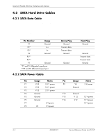
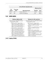
Serial and Parallel ATA Drive Guidelines and Features 4.3 PATA Device Information This information applies to optical drives in a computer having one or two SATA drive controllers and a single PATA drive controller. PATA hard drives are not supported on these models. 4.4 PATA Cables 4.4.1 PATA Data Cable Pin Signal Pin 1 Reset 15 2 Ground 16 3 DD7 17 4 DD8 18 5 DD6 19 6 DD9 20 7 DD5 21 8 DD10 22 9 DD4 23 10 DD11 24 11 DD3 25 12 DD12 26 13 DD2 27 14 DD13 28 4.4.2 PATA Power Cable Signal DD1 DD14 DD0 DD15 Ground (Key) DMARQ Ground DIOW Ground DIOR Ground IORDY CSEL Pin Signal 29 DMAK 30 Ground 31 INTRQ 32 IOCS16 33 DA1 34 PDIAG (cable detect) 35 DA0 36 DA2 37 CS1FX 38 CS3FX 39 DASP 40 Ground Pin Usage 1 +12 V 2 Ground 3 Ground 4 +5 V 4.5 PATA Drive Installation Guidelines The computer system boards for these products have one Parallel ATA (PATA) channel with a single connector. The channel can have up to two devices attached to it. All drives are connected to the channel using an industry-standard 80-conductor cable. ✎ The industry-standard 1.44 MB diskette drive has its own separate channel and is not included as a part of the maximum four ATA drives. Service Reference Guide, dx2100 MT 404569-001 4-3
-
 1
1 -
2
-
3
-
4
-
5
-
6
-
7
-
8
-
9
-
10
-
11
-
12
-
13
-
14
-
15
-
16
-
17
-
18
-
19
-
20
-
21
-
22
-
23
-
24
-
25
-
 26
26 -
 27
27 -
 28
28 -
 29
29 -
 30
30 -
 31
31 -
 32
32 -
 33
33 -
 34
34 -
 35
35 -
 36
36 -
37
-
38
-
39
-
40
-
41
-
42
-
43
-
44
-
45
-
46
-
47
-
48
-
49
-
50
-
51
-
52
-
53
-
54
-
55
-
56
-
57
-
58
-
59
-
60
-
61
-
62
-
63
-
64
-
65
-
66
-
67
-
68
-
69
-
70
-
71
-
72
-
73
-
74
-
75
-
76
-
77
-
78
-
79
-
80
-
81
-
82
-
83
-
84
-
85
-
86
-
87
-
88
-
89
-
90
-
91
-
92
-
93
-
94
-
95
-
96
-
97
-
98
-
99
-
100
-
101
-
102
-
103
-
104
-
105
-
106
-
107
-
108
-
109
-
110
-
111
-
112
-
113
-
114
-
115
-
116
 |
 |
