HP dx2200 HP Compaq dx2200 MT Business PC, 1st Edition - Page 117
Index
 |
View all HP dx2200 manuals
Add to My Manuals
Save this manual to your list of manuals |
Page 117 highlights
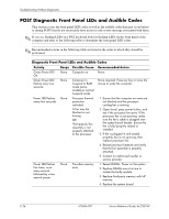
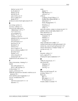
Index 4-pin power pin assignments A-4 24-pin power pin assignments A-4 5.25 drive bezel blank 6-4 A access panel, removal and replacement 6-2 ATA/ATAPI (IDE) drive cable pin assignments A- 4 B battery real-time clock E-2 removal and replacement 6-25 to 6-28 bezel blank, 5.25" drive 6-4 blank screen E-9 C cable connections 6-11 cable management 6-10 cable pinouts PATA data 4-3 PATA power 4-3 SATA data 4-2 SATA power 4-2 cable, proper handling 5-7 cautions AC power 5-1 adding devices 1-1 batteries 5-7 cables 5-7 cooling fan 5-6 installation 1-1 keyboard cleaning 5-5 keyboard keys 5-5 changing operating systems, important information 3-3 changing password 3-4 chassis, illustrated 5-1 cleaning computer 5-4 keyboard 5-5 monitor 5-5 mouse 5-5 cloning tools, software 3-1 CMOS Setup, Standard 2-4 to ??, 2-5 to 2-6 computer cleaning 5-4 pauses E-2 Computer Setup Standard CMOS Setup 2-4 to ??, 2-5 to 2-6 system information 2-4 utilities 2-2 configuring power button 3-2 connector pin assignments A-1 to A-4 country-specific power cord set requirements B-2 customizing software 3-1 D date and time display E-2 deleting password 3-5 deployment tools, software 3-1 device drivers installing/upgrading 1-1 obtaining 1-2 disassembly preparation 6-1 disk, cloning 3-1 drive 5.25" removal and replacement 6-13 capacities 4-5 hard drive removal and replacement 6-16 partition size 4-5 drive bezel 6-4 Drive Key, problems E-23 drive positions 6-12 dual-state power button 3-2 E electrostatic discharge. See ESD energy savings, settings for 3-2 entering supervisor password 3-4 user password 3-4 error messages, POST C-1 to C-5 ESD (electrostatic discharge) information 5-2 Service Reference Guide, dx2200 MT 415606-001 Index-1
-
 1
1 -
2
-
3
-
4
-
5
-
6
-
7
-
8
-
9
-
10
-
11
-
12
-
13
-
14
-
15
-
16
-
17
-
18
-
19
-
20
-
21
-
22
-
23
-
24
-
25
-
26
-
27
-
28
-
29
-
30
-
31
-
32
-
33
-
34
-
35
-
36
-
37
-
38
-
39
-
40
-
41
-
42
-
43
-
44
-
45
-
46
-
47
-
48
-
49
-
50
-
51
-
52
-
53
-
54
-
55
-
56
-
57
-
58
-
59
-
60
-
61
-
62
-
63
-
64
-
65
-
66
-
67
-
68
-
69
-
70
-
71
-
72
-
73
-
74
-
75
-
76
-
77
-
78
-
79
-
80
-
81
-
82
-
83
-
84
-
85
-
86
-
87
-
88
-
89
-
90
-
91
-
92
-
93
-
94
-
95
-
96
-
97
-
98
-
99
-
100
-
101
-
102
-
103
-
104
-
105
-
106
-
107
-
108
-
109
-
110
-
111
-
 112
112 -
 113
113 -
 114
114 -
 115
115 -
 116
116 -
 117
117 -
 118
118 -
 119
119 -
 120
120
 |
 |
