HP dx2200 HP Compaq dx2200 MT Business PC, 1st Edition - Page 118
FailSafe Boot Block ROM
 |
View all HP dx2200 manuals
Add to My Manuals
Save this manual to your list of manuals |
Page 118 highlights
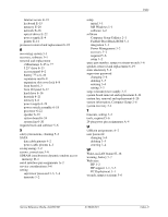
Index materials and equipment 5-3 preventing damage 5-2 Ethernet RJ-45 pin assignments A-1 expansion card removal and replacement 6-8 expansion slot cover lock removal and replacement 6-8 F FailSafe Boot Block ROM 3-1 fan, power supply 5-6 FAT 32 to NTFS conversion 1-2 flashing LEDs C-5 4-pin power pin assignments A-4 front bezel removal and replacement 6-3 front drive bezel 6-4 front I/O panel removal and replacement 6-17 G grounding methods 5-3 H hard drive proper handling 5-7 removal and replacement 6-16 headphone pin assignments A-3 heatsink removal and replacement 6-21 I initial configuration 3-1 Internet addresses, See Web sites K keyboard cleaning 5-5 pin assignments A-1 L LEDs blinking PS/2 keyboard C-5 line-in audio pin assignments A-3 line-out audio pin assignments A-3 M memory, removal and replacement 6-6 microphone pin assignments A-2 monitor blank screen E-9 blurry video E-10 checking connections E-1 cleaning 5-5 dim characters E-10 pin assignments A-3 mouse cleaning 5-5 pin assignments A-1 N NTFS conversion 1-2 O operating systems, important information about 3- 3 P parallel interface pin assignments A-2 password changing 3-4 deleting 3-5 power-on 2-1 setup 3-3 supervisor 3-4 user 3-4 password security 3-3 PATA data cable pinouts 4-3 power cable pinouts 4-3 POST (Power-On Self-Test) 2-1 POST error messages C-1 to C-5 power button configuring 3-2 dual-state 3-2 power cord set requirements country specific B-2 general B-1 Power Management 3-2 power supply fan information 5-6 removal and replacement 6-29 surge-tolerant 3-5 power switch assembly removal and replacement 6-18 power-on password 2-1 Power-On Self-Test (POST) 2-1 preinstalled software image 3-1 preparation for disassembly 6-1 problems audio E-12 CD-ROM and DVD E-22 diskette E-5 display E-9 Drive Key E-23 hard drive E-6 installing hardware E-16 Index-2 415606-001 Service Reference Guide, dx2200 MT
-
 1
1 -
2
-
3
-
4
-
5
-
6
-
7
-
8
-
9
-
10
-
11
-
12
-
13
-
14
-
15
-
16
-
17
-
18
-
19
-
20
-
21
-
22
-
23
-
24
-
25
-
26
-
27
-
28
-
29
-
30
-
31
-
32
-
33
-
34
-
35
-
36
-
37
-
38
-
39
-
40
-
41
-
42
-
43
-
44
-
45
-
46
-
47
-
48
-
49
-
50
-
51
-
52
-
53
-
54
-
55
-
56
-
57
-
58
-
59
-
60
-
61
-
62
-
63
-
64
-
65
-
66
-
67
-
68
-
69
-
70
-
71
-
72
-
73
-
74
-
75
-
76
-
77
-
78
-
79
-
80
-
81
-
82
-
83
-
84
-
85
-
86
-
87
-
88
-
89
-
90
-
91
-
92
-
93
-
94
-
95
-
96
-
97
-
98
-
99
-
100
-
101
-
102
-
103
-
104
-
105
-
106
-
107
-
108
-
109
-
110
-
111
-
112
-
 113
113 -
 114
114 -
 115
115 -
 116
116 -
 117
117 -
 118
118 -
 119
119 -
 120
120
 |
 |