HP mt20 Maintenance and Service Guide - Page 36
Service door
 |
View all HP mt20 manuals
Add to My Manuals
Save this manual to your list of manuals |
Page 36 highlights
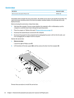
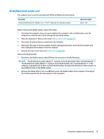
Service door Description Main service door (included in Plastics Kit) Spare part number 905703-001 The bottom of the computer has two service doors. The smaller service door is not used for this product. The main service door provides access to the memory modules, wireless modules, M.2 solid-state drive, and keyboard screws. Before removing the service door, follow these steps: 1. Shut down the computer. If you are unsure whether the computer is off or in Hibernation, turn the computer on, and then shut it down through the operating system. 2. Place the computer in "Battery Safe mode" (Battery Safe mode on page 25). 3. Disconnect all external devices connected to the computer. 4. Disconnect the power from the computer by first unplugging the power cord from the AC outlet, and then unplugging the AC adapter from the computer. Remove the service door: 1. Main service door Loosen the captive Phillips screw (1). 2. Lift the bottom of the door upward (2), and then remove the door from the computer (3). Reverse these procedures to install the service door. 26 Chapter 5 Removal and replacement procedures for Customer Self-Repair parts
-
 1
1 -
2
-
3
-
4
-
5
-
6
-
7
-
8
-
9
-
10
-
11
-
12
-
13
-
14
-
15
-
16
-
17
-
18
-
19
-
20
-
21
-
22
-
23
-
24
-
25
-
26
-
27
-
28
-
29
-
30
-
 31
31 -
 32
32 -
 33
33 -
 34
34 -
 35
35 -
 36
36 -
 37
37 -
 38
38 -
 39
39 -
 40
40 -
 41
41 -
42
-
43
-
44
-
45
-
46
-
47
-
48
-
49
-
50
-
51
-
52
-
53
-
54
-
55
-
56
-
57
-
58
-
59
-
60
-
61
-
62
-
63
-
64
-
65
-
66
-
67
-
68
-
69
-
70
-
71
-
72
-
73
-
74
-
75
-
76
-
77
-
78
-
79
-
80
-
81
-
82
-
83
-
84
-
85
-
86
-
87
-
88
-
89
-
90
-
91
-
92
-
93
-
94
-
95
-
96
-
97
-
98
-
99
-
100
-
101
-
102
-
103
-
104
-
105
-
106
-
107
-
108
 |
 |
