HP mt20 Maintenance and Service Guide - Page 47
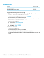
Remove the 4 Phillips PM2.0×3.0 screws, the back of the panel.
 |
View all HP mt20 manuals
Add to My Manuals
Save this manual to your list of manuals |
Page 47 highlights
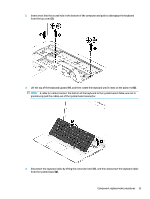
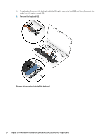
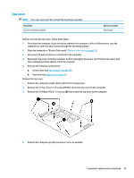
c. Disconnect the cable (2) from the module. 5. To remove the display panel: a. Remove the 4 Phillips PM2.0×3.0 screws (1) that secure the display panel to the enclosure. b. Rotate the display panel onto the keyboard (2) to gain access to the display cable connection on the back of the panel. c. On the back of the display panel, release the adhesive strip that secures the display panel cable to the display panel (1), and then disconnect the cable (2). Component replacement procedures 37
-
 1
1 -
2
-
3
-
4
-
5
-
6
-
7
-
8
-
9
-
10
-
11
-
12
-
13
-
14
-
15
-
16
-
17
-
18
-
19
-
20
-
21
-
22
-
23
-
24
-
25
-
26
-
27
-
28
-
29
-
30
-
31
-
32
-
33
-
34
-
35
-
36
-
37
-
38
-
39
-
40
-
41
-
 42
42 -
 43
43 -
 44
44 -
 45
45 -
 46
46 -
 47
47 -
 48
48 -
 49
49 -
 50
50 -
 51
51 -
 52
52 -
53
-
54
-
55
-
56
-
57
-
58
-
59
-
60
-
61
-
62
-
63
-
64
-
65
-
66
-
67
-
68
-
69
-
70
-
71
-
72
-
73
-
74
-
75
-
76
-
77
-
78
-
79
-
80
-
81
-
82
-
83
-
84
-
85
-
86
-
87
-
88
-
89
-
90
-
91
-
92
-
93
-
94
-
95
-
96
-
97
-
98
-
99
-
100
-
101
-
102
-
103
-
104
-
105
-
106
-
107
-
108
 |
 |

c.
Disconnect the cable
(2)
from the module.
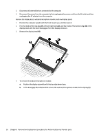
5.
To remove the display panel:
a.
Remove the 4 Phillips PM2.0×3.0 screws
(1)
that secure the display panel to the enclosure.
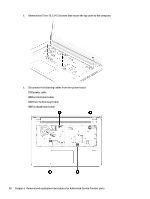
b.
Rotate the display panel onto the keyboard
(2)
to gain access to the display cable connection on
the back of the panel.
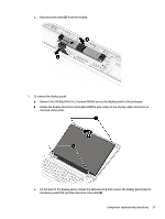
c.
On the back of the display panel, release the adhesive strip that secures the display panel cable to
the display panel
(1)
, and then disconnect the cable
(2)
.
Component replacement procedures
37