HP mt20 Maintenance and Service Guide - Page 57
TouchPad assembly, Remove the 4 Phillips PM2.0×2.0 screws
 |
View all HP mt20 manuals
Add to My Manuals
Save this manual to your list of manuals |
Page 57 highlights
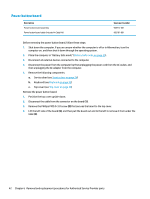
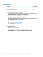
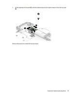
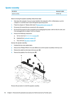
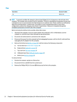
TouchPad assembly Description TouchPad assembly NOTE: The TouchPad is included in the Top Cover spare part kit. TouchPad assembly cable (included in Cable Kit) Spare part number not spared 905707-001 Before removing the TouchPad assembly, follow these steps: 1. Shut down the computer. If you are unsure whether the computer is off or in Hibernation, turn the computer on, and then shut it down through the operating system. 2. Place the computer in "Battery Safe mode" (Battery Safe mode on page 25). 3. Disconnect all external devices connected to the computer. 4. Disconnect the power from the computer by first unplugging the power cord from the AC outlet, and then unplugging the AC adapter from the computer. 5. Remove the following components: a. Service door (see Service door on page 26). b. Keyboard (see Keyboard on page 32) c. Top cover (see Top cover on page 39) Remove the TouchPad assembly: NOTE: Before you remove the TouchPad assembly, make sure nothing (memory card or plastic insert) in installed. 1. Position the top cover upside-down. 2. Disconnect the cable from the connector on the TouchPad (1). 3. Remove the 4 Phillips PM2.0×2.0 screws (2) that secure the TouchPad to the top cover. 4. Rotate the top of the TouchPad upward (3), and then pull the board toward the top of the top cover to remove it (4). Component replacement procedures 47
-
 1
1 -
2
-
3
-
4
-
5
-
6
-
7
-
8
-
9
-
10
-
11
-
12
-
13
-
14
-
15
-
16
-
17
-
18
-
19
-
20
-
21
-
22
-
23
-
24
-
25
-
26
-
27
-
28
-
29
-
30
-
31
-
32
-
33
-
34
-
35
-
36
-
37
-
38
-
39
-
40
-
41
-
42
-
43
-
44
-
45
-
46
-
47
-
48
-
49
-
50
-
51
-
 52
52 -
 53
53 -
 54
54 -
 55
55 -
 56
56 -
 57
57 -
 58
58 -
 59
59 -
 60
60 -
 61
61 -
 62
62 -
63
-
64
-
65
-
66
-
67
-
68
-
69
-
70
-
71
-
72
-
73
-
74
-
75
-
76
-
77
-
78
-
79
-
80
-
81
-
82
-
83
-
84
-
85
-
86
-
87
-
88
-
89
-
90
-
91
-
92
-
93
-
94
-
95
-
96
-
97
-
98
-
99
-
100
-
101
-
102
-
103
-
104
-
105
-
106
-
107
-
108
 |
 |
