HP mt20 Maintenance and Service Guide - Page 70
Display assembly, Remove the 4 Phillips PM2.5×4.0 screws
 |
View all HP mt20 manuals
Add to My Manuals
Save this manual to your list of manuals |
Page 70 highlights
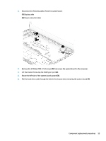
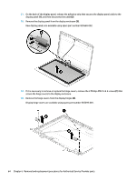
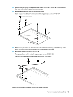
Display assembly Description Display panel assembly, non-touch Non-touch displays are ONLY spared at the subcomponent level. For more information about display components, see Display components on page 17. Spare part number not spared This section describes removing components that require you to completely remove the display panel. For more information about removing display components that do not require that you remove the assembly from the computer, see Display subcomponents (bezel, webcam, panel) on page 35. Before removing the display assembly, follow these steps: 1. Shut down the computer. If you are unsure whether the computer is off or in Hibernation, turn the computer on, and then shut it down through the operating system. 2. Disconnect all external devices connected to the computer. 3. Disconnect the power from the computer by first unplugging the power cord from the AC outlet, and then unplugging the AC adapter from the computer. 4. Remove the following components: a. Service door (see Service door on page 26). b. WLAN module (see WLAN/Bluetooth combo card on page 29) c. Keyboard (see Keyboard on page 32) d. Top cover (see Top cover on page 39) e. USB/audio board (see USB/audio board on page 49) f. Battery (see Battery on page 50) Remove the display assembly: 1. Position the computer upright on a flat surface. 2. Disconnect the display cable from the system board (1). 3. Pull the wireless antennas through the hole in the computer (2). 4. Remove the 4 Phillips PM2.5×4.0 screws (3) from the display hinges. 60 Chapter 6 Removal and replacement procedures for Authorized Service Provider parts
-
 1
1 -
2
-
3
-
4
-
5
-
6
-
7
-
8
-
9
-
10
-
11
-
12
-
13
-
14
-
15
-
16
-
17
-
18
-
19
-
20
-
21
-
22
-
23
-
24
-
25
-
26
-
27
-
28
-
29
-
30
-
31
-
32
-
33
-
34
-
35
-
36
-
37
-
38
-
39
-
40
-
41
-
42
-
43
-
44
-
45
-
46
-
47
-
48
-
49
-
50
-
51
-
52
-
53
-
54
-
55
-
56
-
57
-
58
-
59
-
60
-
61
-
62
-
63
-
64
-
 65
65 -
 66
66 -
 67
67 -
 68
68 -
 69
69 -
 70
70 -
 71
71 -
 72
72 -
 73
73 -
 74
74 -
 75
75 -
76
-
77
-
78
-
79
-
80
-
81
-
82
-
83
-
84
-
85
-
86
-
87
-
88
-
89
-
90
-
91
-
92
-
93
-
94
-
95
-
96
-
97
-
98
-
99
-
100
-
101
-
102
-
103
-
104
-
105
-
106
-
107
-
108
 |
 |
