HP mt20 Maintenance and Service Guide - Page 45
Removal and replacement procedures for Authorized Service Provider parts, Component replacement
 |
View all HP mt20 manuals
Add to My Manuals
Save this manual to your list of manuals |
Page 45 highlights
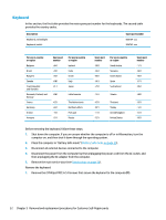
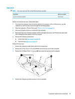
6 Removal and replacement procedures for Authorized Service Provider parts CAUTION: Components described in this chapter should only be accessed by an authorized service provider. Accessing these parts can damage the computer or void the warranty. NOTE: HP continually improves and changes product parts. For complete and current information on supported parts for your computer, go to http://partsurfer.hp.com, select your country or region, and then follow the on-screen instructions. Component replacement procedures NOTE: Details about your computer, including model, serial number, product key, and length of warranty, are on the service tag at the bottom of your computer. See Labels on page 13 for details. This chapter provides removal and replacement procedures for Authorized Service Provider only parts. There are as many as 57 screws that must be removed, replaced, or loosened when servicing Authorized Service Provider only parts. Make special note of each screw size and location during removal and replacement. Display subcomponents (bezel, webcam, panel) This section describes removing display subcomponents that do not require that you remove the entire display assembly from the computer. You can remove the display bezel, webcam/microphone module, and display panel while the display assembly is still attached to the computer. To remove the remaining display subcomponents, you must remove the entire display assembly from the computer. See Display assembly on page 60 for more information about removing the display assembly in its entirety. Description Raw display panel HD Display bezel Models without a webcam Models with a webcam Webcam/microphone module Spare part number 839668-002 905693-001 905692-001 826271-002 Before removing display subcomponents while the display assembly is still attached to the computer, follow these steps: 1. Shut down the computer. If you are unsure whether the computer is off or in Hibernation, turn the computer on, and then shut it down through the operating system. 2. Place the computer in "Battery Safe mode" (Battery Safe mode on page 25). Component replacement procedures 35
-
 1
1 -
2
-
3
-
4
-
5
-
6
-
7
-
8
-
9
-
10
-
11
-
12
-
13
-
14
-
15
-
16
-
17
-
18
-
19
-
20
-
21
-
22
-
23
-
24
-
25
-
26
-
27
-
28
-
29
-
30
-
31
-
32
-
33
-
34
-
35
-
36
-
37
-
38
-
39
-
 40
40 -
 41
41 -
 42
42 -
 43
43 -
 44
44 -
 45
45 -
 46
46 -
 47
47 -
 48
48 -
 49
49 -
 50
50 -
51
-
52
-
53
-
54
-
55
-
56
-
57
-
58
-
59
-
60
-
61
-
62
-
63
-
64
-
65
-
66
-
67
-
68
-
69
-
70
-
71
-
72
-
73
-
74
-
75
-
76
-
77
-
78
-
79
-
80
-
81
-
82
-
83
-
84
-
85
-
86
-
87
-
88
-
89
-
90
-
91
-
92
-
93
-
94
-
95
-
96
-
97
-
98
-
99
-
100
-
101
-
102
-
103
-
104
-
105
-
106
-
107
-
108
 |
 |
