HP mt20 Maintenance and Service Guide - Page 65
Remove the 3 Phillips PM2.5×5.0 screws, Rotate the left side of the system board upward
 |
View all HP mt20 manuals
Add to My Manuals
Save this manual to your list of manuals |
Page 65 highlights
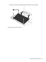
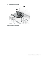
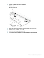
2. Disconnect the following cables from the system board: (1) Display cable (2) Power connector cable 3. Remove the 3 Phillips PM2.5×5.0 screws (1) that secure the system board to the computer. 4. Lift the bracket from atop the USB-Type C port (2). 5. Rotate the left side of the system board upward (3). 6. Pull the hard drive cable through the hole in the chassis when removing the system board (4). Component replacement procedures 55
-
 1
1 -
2
-
3
-
4
-
5
-
6
-
7
-
8
-
9
-
10
-
11
-
12
-
13
-
14
-
15
-
16
-
17
-
18
-
19
-
20
-
21
-
22
-
23
-
24
-
25
-
26
-
27
-
28
-
29
-
30
-
31
-
32
-
33
-
34
-
35
-
36
-
37
-
38
-
39
-
40
-
41
-
42
-
43
-
44
-
45
-
46
-
47
-
48
-
49
-
50
-
51
-
52
-
53
-
54
-
55
-
56
-
57
-
58
-
59
-
 60
60 -
 61
61 -
 62
62 -
 63
63 -
 64
64 -
 65
65 -
 66
66 -
 67
67 -
 68
68 -
 69
69 -
 70
70 -
71
-
72
-
73
-
74
-
75
-
76
-
77
-
78
-
79
-
80
-
81
-
82
-
83
-
84
-
85
-
86
-
87
-
88
-
89
-
90
-
91
-
92
-
93
-
94
-
95
-
96
-
97
-
98
-
99
-
100
-
101
-
102
-
103
-
104
-
105
-
106
-
107
-
108
 |
 |

2.
Disconnect the following cables from the system board:
(1)
Display cable
(2)
Power connector cable
3.
Remove the 3 Phillips PM2.5×5.0 screws
(1)
that secure the system board to the computer.
4.
Lift the bracket from atop the USB-Type C port
(2)
.
5.
Rotate the left side of the system board upward
(3)
.
6.
Pull the hard drive cable through the hole in the chassis when removing the system board
(4)
.
Component replacement procedures
55