Hitachi 7K320 Specifications - Page 6
Table 65 Number of cylinders/heads/sectors by models for HTS7232XXL9SA8X / HTS7232XXL9A38X - 80
 |
UPC - 890552647200
View all Hitachi 7K320 manuals
Add to My Manuals
Save this manual to your list of manuals |
Page 6 highlights
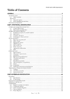
7K320 SATA OEM Specification Table 17. Random vibration PSD profile breakpoints (operating) 34 Table 18. Swept sine vibration 34 Table 19. Random Vibration PSD Profile Breakpoints (nonoperating) 35 Table 20. Operating shock 35 Table 21. Nonoperating shock 35 Table 22. Weighted sound power 36 Table 23. Interface connector pins and I/O signals 40 Table 24 Register naming convention and correspondence 45 Table 25 Device Control Register 45 Table 26 Device Register 46 Table 27 Error Register 46 Table 28 Status Register 47 Table 29 Reset Response Table 49 Table 30 Default Register Values 50 Table 31 Diagnostic Codes 50 Table 32 Reset error register values 50 Table 33 Device's behavior by ATA commands 51 Table 34 Power conditions 53 Table 35 Command table for device lock operation 61 Table 36 Command table for device lock operation - continued 62 Table 37 Set Max Set Password data content 64 Table 38 Preserved Software Setting 68 Table 39 SCT Action Code Supported 68 Table 40 Command set 72 Table 41 Command Set - continued 73 Table 42 Command Set (Subcommand) 74 Table 43 Check Power Mode Command (E5h/98h) 76 Table 44 Device Configuration Overlay Command (B1h) 77 Table 45 Device Configuration Overlay Features register values 77 Table 46 Device Configuration Overlay Data structure 79 Table 47 DCO error information definition 80 Table 48 Download Command (92h) 81 Table 49 Execute Device Diagnostic Command (90h) 83 Table 50 Flush Cache Command (E7h) 84 Table 51 Flush Cache EXT Command (EAh) 85 Table 52 Format Track Command (50h) 86 Table 53 Format Unit Command (F7h) 87 Table 54 Identify Device Command (ECh) 88 Table 55 Identify device information 89 Table 56 Identify device information --- Continued --- 90 Table 57 Identify device information --- Continued --- 91 Table 58 Identify device information --- Continued --- 92 Table 59 Identify device information --- Continued --- 93 Table 60 Identify device information --- Continued --- 94 Table 61 Identify device information --- Continued --- 95 Table 62 Identify device information --- Continued --- 96 Table 63 Identify device information --- Continued --- 98 Table 64 Number of cylinders/heads/sectors by models for HTS7232XXL9SA6X / HTS7232XXL9A36X 99 Table 65 Number of cylinders/heads/sectors by models for HTS7232XXL9SA8X / HTS7232XXL9A38X 100 Table 66 Idle Command (E3h/97h) 101 Table 67 Idle Immediate Command (E1h/95h) 102 Table 68 Initialize Device Parameters Command (91h) 103 Table 69 Read Buffer Command (E4h) 104 Table 70 Read DMA Command (C8h/C9h) 105 Table 71 Read DMA Ext Command (25h) 106 Table 72 Read FPDMA Queued Command (60h) 107 Table 73 Read Log Ext Command (2Fh) 108 Table 74 Log address definition 108 Table 75 General purpose Log Directory 109 Table 76 Extended comprehensive SMART error Log 110 Table 77 Extended Error log data structure 110 Table 78 Command data structure 111 Page 6 of 176
-
 1
1 -
 2
2 -
 3
3 -
 4
4 -
 5
5 -
 6
6 -
 7
7 -
 8
8 -
 9
9 -
 10
10 -
 11
11 -
 12
12 -
13
-
14
-
15
-
16
-
17
-
18
-
19
-
20
-
21
-
22
-
23
-
24
-
25
-
26
-
27
-
28
-
29
-
30
-
31
-
32
-
33
-
34
-
35
-
36
-
37
-
38
-
39
-
40
-
41
-
42
-
43
-
44
-
45
-
46
-
47
-
48
-
49
-
50
-
51
-
52
-
53
-
54
-
55
-
56
-
57
-
58
-
59
-
60
-
61
-
62
-
63
-
64
-
65
-
66
-
67
-
68
-
69
-
70
-
71
-
72
-
73
-
74
-
75
-
76
-
77
-
78
-
79
-
80
-
81
-
82
-
83
-
84
-
85
-
86
-
87
-
88
-
89
-
90
-
91
-
92
-
93
-
94
-
95
-
96
-
97
-
98
-
99
-
100
-
101
-
102
-
103
-
104
-
105
-
106
-
107
-
108
-
109
-
110
-
111
-
112
-
113
-
114
-
115
-
116
-
117
-
118
-
119
-
120
-
121
-
122
-
123
-
124
-
125
-
126
-
127
-
128
-
129
-
130
-
131
-
132
-
133
-
134
-
135
-
136
-
137
-
138
-
139
-
140
-
141
-
142
-
143
-
144
-
145
-
146
-
147
-
148
-
149
-
150
-
151
-
152
-
153
-
154
-
155
-
156
-
157
-
158
-
159
-
160
-
161
-
162
-
163
-
164
-
165
-
166
-
167
-
168
-
169
-
170
-
171
-
172
-
173
-
174
-
175
-
176
 |
 |
