IBM 86481BU Installation Guide - Page 83
Erasing, forgotten, password, clearing
 |
View all IBM 86481BU manuals
Add to My Manuals
Save this manual to your list of manuals |
Page 83 highlights
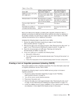
Table 4. Error LEDs Error LED Without optional Remote Supervisor Adapter II DIMM error (D16, D17, D18, Memory problem (also lights D19, D20, D21) the system-error LED on the front bezel) Microprocessor 2 error (D22) Microprocessor 2 problem (also lights the system-error LED on the front bezel) Fan error (D25, D26, D27, D29) No function Hard disk error (LEDs on hot-swap hard disk drives) Hot-swap hard disk drive failure With optional Remote Supervisor Adapter II Memory problem (also lights the system-error LED on the front bezel) Microprocessor 2 problem (also lights the system-error LED on the front bezel) Fan failure Hot-swap hard disk drive failure Each error LED is lit to indicate a problem with a specific component. After a problem is corrected, its LED will not be lit the next time the server is restarted; if the problem remains, the LED will be lit again. See the User's Guide on the IBM xSeries Documentation CD for additional information. Complete the following steps to view the lit error LEDs: 1. Review the safety information beginning on page vii and "Handling static-sensitive devices" on page 12. 2. Remove the side cover and support bracket. (See "Removing the side cover" on page 13 and "Removing and installing the support bracket" on page 14.) 3. Open the microprocessor air baffle (see "Opening and closing the microprocessor air baffle" on page 15). 4. If any error LEDs are lit, complete the following steps: a. Note which LEDs are lit. b. Turn off the server and all attached devices (see "Turning off the server" on page 46). c. Follow the instructions in the troubleshooting charts for those components. Erasing a lost or forgotten password (clearing CMOS) This section applies to lost or forgotten passwords. For more information about lost or forgotten passwords, see the User's Guide. Complete the following steps to set the CMOS recovery jumper and erase a forgotten password: 1. Review the safety information beginning on page vii and "Handling static-sensitive devices" on page 12. 2. Turn off the server and all attached devices. 3. Disconnect the power cord. 4. Remove the side cover and support bracket. (See "Removing the side cover" on page 13 and "Removing and installing the support bracket" on page 14.) 5. Locate the CMOS recovery jumper (JCMOS1) on the system board, removing any adapters or other objects that impede access to the jumper. Chapter 6. Solving problems 69
-
 1
1 -
2
-
3
-
4
-
5
-
6
-
7
-
8
-
9
-
10
-
11
-
12
-
13
-
14
-
15
-
16
-
17
-
18
-
19
-
20
-
21
-
22
-
23
-
24
-
25
-
26
-
27
-
28
-
29
-
30
-
31
-
32
-
33
-
34
-
35
-
36
-
37
-
38
-
39
-
40
-
41
-
42
-
43
-
44
-
45
-
46
-
47
-
48
-
49
-
50
-
51
-
52
-
53
-
54
-
55
-
56
-
57
-
58
-
59
-
60
-
61
-
62
-
63
-
64
-
65
-
66
-
67
-
68
-
69
-
70
-
71
-
72
-
73
-
74
-
75
-
76
-
77
-
 78
78 -
 79
79 -
 80
80 -
 81
81 -
 82
82 -
 83
83 -
 84
84 -
 85
85 -
 86
86 -
 87
87 -
 88
88 -
89
-
90
-
91
-
92
-
93
-
94
-
95
-
96
-
97
-
98
-
99
-
100
-
101
-
102
-
103
-
104
-
105
-
106
-
107
-
108
-
109
-
110
-
111
-
112
-
113
-
114
-
115
-
116
-
117
-
118
 |
 |
