IBM 86803RU Hardware Maintenance Manual - Page 121
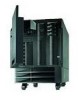
Insert the replacement fan assembly in the front, access cover.
 |
UPC - 087944453369
View all IBM 86803RU manuals
Add to My Manuals
Save this manual to your list of manuals |
Page 121 highlights
3. Pull on the fastener 1 and remove the fan assembly from the server. 4. Insert the replacement fan assembly in the server. Align the bottom edge of the fan assembly with the matching openings in the server chassis. 5. When you have the fan assembly correctly seated, press on the fastener to secure the fan assembly in the server. Note The power cable engages and the fan blades begin to spin when you correctly seat the fan assembly in the chassis. 6. To replace a fan assembly in the front access cover, remove the front bezel (see "Removing the Front Bezel" on page 163). 7. Pull on the fastener and remove the fan assembly 1 from the front access cover. 8. Insert the replacement fan assembly in the front access cover. Align the bottom edge of the fan assembly 2 with the matching openings in the front access cover. 9. When you have the fan assembly correctly seated, press on the fastener to secure the fan assembly. Note The power cable engages and the fan blades begin to spin when you correctly seat the fan assembly. 10. If you have other options to install or remove, do so now; otherwise, go to "Completing the Installation" on page 97. Netfinity 7000-M10 - Type 8680 113
-
 1
1 -
2
-
3
-
4
-
5
-
6
-
7
-
8
-
9
-
10
-
11
-
12
-
13
-
14
-
15
-
16
-
17
-
18
-
19
-
20
-
21
-
22
-
23
-
24
-
25
-
26
-
27
-
28
-
29
-
30
-
31
-
32
-
33
-
34
-
35
-
36
-
37
-
38
-
39
-
40
-
41
-
42
-
43
-
44
-
45
-
46
-
47
-
48
-
49
-
50
-
51
-
52
-
53
-
54
-
55
-
56
-
57
-
58
-
59
-
60
-
61
-
62
-
63
-
64
-
65
-
66
-
67
-
68
-
69
-
70
-
71
-
72
-
73
-
74
-
75
-
76
-
77
-
78
-
79
-
80
-
81
-
82
-
83
-
84
-
85
-
86
-
87
-
88
-
89
-
90
-
91
-
92
-
93
-
94
-
95
-
96
-
97
-
98
-
99
-
100
-
101
-
102
-
103
-
104
-
105
-
106
-
107
-
108
-
109
-
110
-
111
-
112
-
113
-
114
-
115
-
 116
116 -
 117
117 -
 118
118 -
 119
119 -
 120
120 -
 121
121 -
 122
122 -
 123
123 -
 124
124 -
 125
125 -
 126
126 -
127
-
128
-
129
-
130
-
131
-
132
-
133
-
134
-
135
-
136
-
137
-
138
-
139
-
140
-
141
-
142
-
143
-
144
-
145
-
146
-
147
-
148
-
149
-
150
-
151
-
152
-
153
-
154
-
155
-
156
-
157
-
158
-
159
-
160
-
161
-
162
-
163
-
164
-
165
-
166
-
167
-
168
-
169
-
170
-
171
-
172
-
173
-
174
-
175
-
176
-
177
-
178
-
179
-
180
-
181
-
182
-
183
-
184
-
185
-
186
-
187
-
188
-
189
-
190
-
191
-
192
-
193
-
194
-
195
-
196
-
197
-
198
-
199
-
200
-
201
-
202
-
203
-
204
-
205
-
206
-
207
-
208
-
209
-
210
-
211
-
212
-
213
-
214
-
215
-
216
-
217
-
218
-
219
-
220
-
221
-
222
-
223
-
224
-
225
-
226
-
227
-
228
-
229
-
230
-
231
-
232
-
233
-
234
-
235
-
236
-
237
-
238
-
239
-
240
-
241
-
242
-
243
-
244
-
245
-
246
-
247
-
248
-
249
-
250
-
251
-
252
-
253
-
254
-
255
-
256
-
257
-
258
-
259
-
260
-
261
-
262
-
263
-
264
-
265
-
266
-
267
-
268
-
269
-
270
-
271
-
272
-
273
-
274
-
275
-
276
-
277
-
278
 |
 |
