IBM 8852 User Guide - Page 25
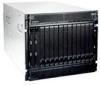
Major components of the BladeCenter H unit - bladecenter h chassis
 |
UPC - 883436027069
View all IBM 8852 manuals
Add to My Manuals
Save this manual to your list of manuals |
Page 25 highlights
Major components of the BladeCenter H unit The following illustrations show the locations of the major components in the BladeCenter unit. I/O module Management module I/O module filler Description and Action Power Module LEDs AC OK DC OK Management module filler I/O module filler Blade filler System service card Media tray Optical drive Fan pack 4th power module Handle (open) BladeCenter® Service Information Light Path Diagnostics BladeCenter System LED Panel - Primary See hardware for actual location of LEDs and buttons. Blade Server Control Panel - Secondary See hardware for actual location of LEDs and buttons. CD Hot-Swap Power Module 3rd power module Blower module I/O module filler Chassis Bezel, top and bottom Power module, 2900 W Power module, 2980 W (With integrated fan pack) Power module filler Chapter 1. Introduction 9
-
 1
1 -
2
-
3
-
4
-
5
-
6
-
7
-
8
-
9
-
10
-
11
-
12
-
13
-
14
-
15
-
16
-
17
-
18
-
19
-
 20
20 -
 21
21 -
 22
22 -
 23
23 -
 24
24 -
 25
25 -
 26
26 -
 27
27 -
 28
28 -
 29
29 -
 30
30 -
31
-
32
-
33
-
34
-
35
-
36
-
37
-
38
-
39
-
40
-
41
-
42
-
43
-
44
-
45
-
46
-
47
-
48
-
49
-
50
-
51
-
52
-
53
-
54
-
55
-
56
-
57
-
58
-
59
-
60
-
61
-
62
-
63
-
64
-
65
-
66
-
67
-
68
-
69
-
70
-
71
-
72
-
73
-
74
-
75
-
76
-
77
-
78
-
79
-
80
-
81
-
82
 |
 |
