IBM 8852 User Guide - Page 28
BladeCenter components, controls, and LEDs, Front view, Power modules
 |
UPC - 883436027069
View all IBM 8852 manuals
Add to My Manuals
Save this manual to your list of manuals |
Page 28 highlights
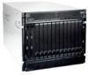
BladeCenter components, controls, and LEDs This section identifies the components, controls, and LEDs on the front and rear of the BladeCenter unit. Front view This section identifies the components, controls, and LEDs on the front of the BladeCenter unit. Power module 1 Power module bay 3 Blade server control panel Media tray Front system LED panel System service cards Optical drive activity LED Optical drive eject button USB connectors Power module 2 Power modules The following illustration shows the LEDs on each power module. AC power LED Power module error LED Power module bay 4 DC power LED Fan error LED The LEDs on each power module indicate the condition of the power module and fan pack. Note: The orientation of the power module shown in the illustration is for one of the top power-modules. The orientation for modules in the bottom power-module bays is rotated 180°. v DC power LED: When this green LED is lit, the dc output from the power module to the other components and blade servers is present and within specifications. During typical operation, both the ac power and dc power LEDs are lit. v AC power LED: When this green LED is lit, ac input to the power module is present and within specifications. During typical operation, both the ac power and dc power LEDs are lit. 12 BladeCenter H Type 8852, 7989, and 1886: Installation and User's Guide
-
 1
1 -
2
-
3
-
4
-
5
-
6
-
7
-
8
-
9
-
10
-
11
-
12
-
13
-
14
-
15
-
16
-
17
-
18
-
19
-
20
-
21
-
22
-
 23
23 -
 24
24 -
 25
25 -
 26
26 -
 27
27 -
 28
28 -
 29
29 -
 30
30 -
 31
31 -
 32
32 -
 33
33 -
34
-
35
-
36
-
37
-
38
-
39
-
40
-
41
-
42
-
43
-
44
-
45
-
46
-
47
-
48
-
49
-
50
-
51
-
52
-
53
-
54
-
55
-
56
-
57
-
58
-
59
-
60
-
61
-
62
-
63
-
64
-
65
-
66
-
67
-
68
-
69
-
70
-
71
-
72
-
73
-
74
-
75
-
76
-
77
-
78
-
79
-
80
-
81
-
82
 |
 |
