IBM 88743RU User Guide - Page 38
Installing, adapter
 |
UPC - 000435945938
View all IBM 88743RU manuals
Add to My Manuals
Save this manual to your list of manuals |
Page 38 highlights
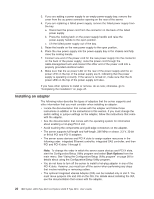
3. If you are adding a power supply to an empty power-supply bay, remove the cover from the ac power connector opening on the rear of the server. 4. If you are replacing a failed power supply, remove the failed power supply from the bay: a. Disconnect the power cord from the connector on the back of the failed power supply. b. Press the locking latch on the power-supply handle and raise the power-supply handle to the open position. c. Lift the failed power supply out of the bay. 5. Raise the handle on the new power supply to the open position. 6. Place the new power supply into the power-supply bay in the chassis and fully close the locking handle. 7. Connect one end of the power cord for the new power supply into the connector on the back of the power supply; route the power cord through the cable-management arm and connect the other end of the power cord into a properly grounded electrical outlet. 8. Make sure that the ac power LED on the rear of the power supply and the ac power LED on the top of the power supply are lit, indicating that the power supply is operating correctly. If the server is turned on, make sure that the dc power LED on the top of the power supply is lit also. If you have other options to install or remove, do so now; otherwise, go to "Completing the installation" on page 47. Installing an adapter The following notes describe the types of adapters that the server supports and other information that you must consider when installing an adapter: v Locate the documentation that comes with the adapter and follow those instructions in addition to the instructions in this section. If you must change the switch setting or jumper settings on the adapter, follow the instructions that come with the adapter. v See the documentation that comes with the operating system for information about enabling a hot-plug PCI-X slot. v Avoid touching the components and gold-edge connectors on the adapter. v The server supports full-length and half-length, 266 MHz or slower, 3.3 V, 32-bit or 64-bit PCI and PCI-X adapters. v The server scans devices and PCI-X slots to assign system resources in the following order: integrated Ethernet controller, integrated SAS controller, and then PCI and PCI-X slots 1 through 6. Note: To change the order in which the server scans devices and PCI-X slots, start the Configuration/Setup Utility program and select Start Options from the main menu. See "Using the Configuration/Setup Utility program" on page 58 for details about using the Configuration/Setup Utility program. v You do not have to turn off the server to install a hot-plug adapter in any of the PCI-X slots. However, you must turn off the server when performing any steps that involve installing or removing cables. v The optional Integrated xSeries Adapter (IXA) can be installed only in slot 2. You must move jumpers J35 and J40 on the IXA. For details about installing the IXA, see the documentation that comes with the adapter. 26 IBM System x3950 Type 8878 and System x3950 E Type 8879: User's Guide
-
 1
1 -
2
-
3
-
4
-
5
-
6
-
7
-
8
-
9
-
10
-
11
-
12
-
13
-
14
-
15
-
16
-
17
-
18
-
19
-
20
-
21
-
22
-
23
-
24
-
25
-
26
-
27
-
28
-
29
-
30
-
31
-
32
-
 33
33 -
 34
34 -
 35
35 -
 36
36 -
 37
37 -
 38
38 -
 39
39 -
 40
40 -
 41
41 -
 42
42 -
 43
43 -
44
-
45
-
46
-
47
-
48
-
49
-
50
-
51
-
52
-
53
-
54
-
55
-
56
-
57
-
58
-
59
-
60
-
61
-
62
-
63
-
64
-
65
-
66
-
67
-
68
-
69
-
70
-
71
-
72
-
73
-
74
-
75
-
76
-
77
-
78
-
79
-
80
-
81
-
82
-
83
-
84
-
85
-
86
-
87
-
88
-
89
-
90
-
91
-
92
-
93
-
94
-
95
-
96
-
97
-
98
-
99
-
100
-
101
-
102
-
103
-
104
-
105
-
106
-
107
-
108
-
109
-
110
 |
 |
