IBM 88743RU User Guide - Page 67
cable-management
 |
UPC - 000435945938
View all IBM 88743RU manuals
Add to My Manuals
Save this manual to your list of manuals |
Page 67 highlights
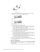
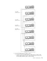
b. Locate the SMP Expansion cable that is connected to port 2 on node 3; then, connect the opposite end of the cable to port 2 of node 6. Next, route the cable through the node 6 cable-management arm. c. Locate the SMP Expansion cable that is connected to port 3 on node 5; then, connect the opposite end of the cable to port 3 of node 6. Next, route the cable through the node 6 cable-management arm. 9. Connect the SMP Expansion cables to node 7: a. Locate the SMP Expansion cable that is connected to port 1 on node 6; then, connect the opposite end of the cable to port 1 of node 7. Next, route the cable through the node 7 cable-management arm. b. Locate the SMP Expansion cable that is connected to port 2 on node 2; then, connect the opposite end of the cable to port 2 of node 7. Next, route the cable through the node 7 cable-management arm. c. Connect one end of an SMP Expansion cable to port 3 on node 7; then, route the cable through the node 7 cable-management arm. Use a 2.3-m (7.6-foot) SMP Expansion cable for this connection. 10. Connect the SMP Expansion cables to node 8: a. Locate the SMP Expansion cable that is connected to port 1 on node 5; then, connect the opposite end of the cable to port 1 of node 8. Next, route the cable through the node 8 cable-management arm. b. Locate the SMP Expansion cable that is connected to port 2 on node 4; then, connect the opposite end of the cable to port 2 of node 8. Next, route the cable through the node 8 cable-management arm. c. Locate the SMP Expansion cable that is connected to port 3 on node 7; then, connect the opposite end of the cable to port 3 of node 8. Next, route the cable through the node 8 cable-management arm. 11. Route any remaining cables through the cable-management arms. 12. Secure the cables in the cable-management arms with the hook-and-loop straps that come with the server. Chapter 2. Installing options 55
-
 1
1 -
2
-
3
-
4
-
5
-
6
-
7
-
8
-
9
-
10
-
11
-
12
-
13
-
14
-
15
-
16
-
17
-
18
-
19
-
20
-
21
-
22
-
23
-
24
-
25
-
26
-
27
-
28
-
29
-
30
-
31
-
32
-
33
-
34
-
35
-
36
-
37
-
38
-
39
-
40
-
41
-
42
-
43
-
44
-
45
-
46
-
47
-
48
-
49
-
50
-
51
-
52
-
53
-
54
-
55
-
56
-
57
-
58
-
59
-
60
-
61
-
 62
62 -
 63
63 -
 64
64 -
 65
65 -
 66
66 -
 67
67 -
 68
68 -
 69
69 -
 70
70 -
 71
71 -
 72
72 -
73
-
74
-
75
-
76
-
77
-
78
-
79
-
80
-
81
-
82
-
83
-
84
-
85
-
86
-
87
-
88
-
89
-
90
-
91
-
92
-
93
-
94
-
95
-
96
-
97
-
98
-
99
-
100
-
101
-
102
-
103
-
104
-
105
-
106
-
107
-
108
-
109
-
110
 |
 |
