IBM 88743RU User Guide - Page 60
Connecting, cables
 |
UPC - 000435945938
View all IBM 88743RU manuals
Add to My Manuals
Save this manual to your list of manuals |
Page 60 highlights
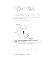
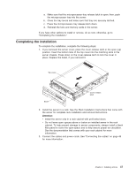
Connecting the cables You must turn off the server (see "Server power features" on page 12) before connecting any cables to or disconnecting any cables from the server. See the documentation that comes with optional devices for additional cabling instructions. It might be easier for you to route cables before you install certain options. Cable identifiers are printed on the cables that come with the server and options. Use these identifiers to connect the cables to the correct connectors. For details about the location and function of the input and output connectors, see "Server controls, connectors, LEDs, and power" on page 9. Two optional SMP Expansion cable kits are available to interconnect the SMP Expansion Ports of two or more servers: v 2.3 m XpandOnDemand™ Scalability cable kit (comes with one 2.3-m (7.6-foot) SMP Expansion cable) v 2.9 m XpandOnDemand Scalability cable kit (comes with one 2.9-m (9.5-foot) SMP Expansion cable) The following illustrations show the locations of the input and output connectors on the server. Detailed cabling instructions are in the Rack Installation Instructions that come with the server. Rear view SP Ethernet 10/100 Power-supply USB 1 Video USB 2 System serial SP serial SMP expansion port 1 SMP expansion port 2 SMP expansion port 3 Front view Power-control button USB connector Mouse Keyboard IXA RS 485 Gigabit Ethernet 2 Gigabit Ethernet 1 Information LED Release latch Power-on LED Hard disk drive activity LED Locator LED System-error LED 48 IBM System x3950 Type 8878 and System x3950 E Type 8879: User's Guide
-
 1
1 -
2
-
3
-
4
-
5
-
6
-
7
-
8
-
9
-
10
-
11
-
12
-
13
-
14
-
15
-
16
-
17
-
18
-
19
-
20
-
21
-
22
-
23
-
24
-
25
-
26
-
27
-
28
-
29
-
30
-
31
-
32
-
33
-
34
-
35
-
36
-
37
-
38
-
39
-
40
-
41
-
42
-
43
-
44
-
45
-
46
-
47
-
48
-
49
-
50
-
51
-
52
-
53
-
54
-
 55
55 -
 56
56 -
 57
57 -
 58
58 -
 59
59 -
 60
60 -
 61
61 -
 62
62 -
 63
63 -
 64
64 -
 65
65 -
66
-
67
-
68
-
69
-
70
-
71
-
72
-
73
-
74
-
75
-
76
-
77
-
78
-
79
-
80
-
81
-
82
-
83
-
84
-
85
-
86
-
87
-
88
-
89
-
90
-
91
-
92
-
93
-
94
-
95
-
96
-
97
-
98
-
99
-
100
-
101
-
102
-
103
-
104
-
105
-
106
-
107
-
108
-
109
-
110
 |
 |
