IBM 88743RU User Guide - Page 58
installing
 |
UPC - 000435945938
View all IBM 88743RU manuals
Add to My Manuals
Save this manual to your list of manuals |
Page 58 highlights
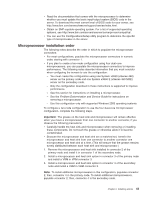
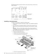
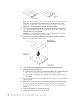
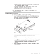
Lever closed Lever fully open Note: Two of the microprocessor sockets are mounted on the microprocessor board with the microprocessor-release lever on the opposite side. These sockets are rotated 180° on the microprocessor board. Be sure to verify the orientation of the socket before installing the microprocessor. 8. Touch the static-protective package that contains the new microprocessor to any unpainted metal surface on the outside of the server; then, remove the microprocessor from the package. Attention: To avoid bending the pins on the microprocessor, do not use excessive force when pressing it into the socket 9. Position the microprocessor over the microprocessor socket and carefully press the microprocessor into the socket. Microprocessor Microprocessor orientation indicator Microprocessor connector Microprocessorrelease lever 10. Close the microprocessor-release lever to secure the microprocessor. 11. Open the heat-sink retaining clip: a. Press down on the center of the heat-sink retaining clip. This will cause the clip to flex and release it from the tabs on the heat-sink socket. b. Lift the heat-sink retaining clip to the fully open position (approximately 135° angle). 12. Remove the heat sink from its package and remove the cover from the bottom of the heat sink. 13. Remove the release liner and orient the heat sink above the microprocessor; then, press the heat sink into place and close the heat-sink release lever. 14. If you have other microprocessors to install, do so now by repeating steps 5 through 13. 15. Install the air baffle in the microprocessor tray. 16. Reinstall the microprocessor tray in the server: 46 IBM System x3950 Type 8878 and System x3950 E Type 8879: User's Guide
-
 1
1 -
2
-
3
-
4
-
5
-
6
-
7
-
8
-
9
-
10
-
11
-
12
-
13
-
14
-
15
-
16
-
17
-
18
-
19
-
20
-
21
-
22
-
23
-
24
-
25
-
26
-
27
-
28
-
29
-
30
-
31
-
32
-
33
-
34
-
35
-
36
-
37
-
38
-
39
-
40
-
41
-
42
-
43
-
44
-
45
-
46
-
47
-
48
-
49
-
50
-
51
-
52
-
 53
53 -
 54
54 -
 55
55 -
 56
56 -
 57
57 -
 58
58 -
 59
59 -
 60
60 -
 61
61 -
 62
62 -
 63
63 -
64
-
65
-
66
-
67
-
68
-
69
-
70
-
71
-
72
-
73
-
74
-
75
-
76
-
77
-
78
-
79
-
80
-
81
-
82
-
83
-
84
-
85
-
86
-
87
-
88
-
89
-
90
-
91
-
92
-
93
-
94
-
95
-
96
-
97
-
98
-
99
-
100
-
101
-
102
-
103
-
104
-
105
-
106
-
107
-
108
-
109
-
110
 |
 |
