IBM 88743RU User Guide - Page 64
Eight-node, configuration
 |
UPC - 000435945938
View all IBM 88743RU manuals
Add to My Manuals
Save this manual to your list of manuals |
Page 64 highlights
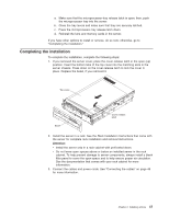
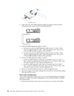
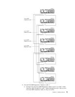
b. Connect one end of an SMP Expansion cable to port 2 on node 2; then, route the cable through the node 2 cable-management arm. Use a 2.3-m (7.6-foot) SMP Expansion cable for this connection. c. Locate the SMP Expansion cable that is connected to port 3 on node 1; then, connect the opposite end of the cable to port 3 of node 2. Next, route the cable through the node 2 cable-management arm. 5. Connect the SMP Expansion cables to node 3: a. Locate the SMP Expansion cable that is connected to port 1 on node 2; then, connect the opposite end of the cable to port 1 of node 3. Next, route the cable through the node 3 cable-management arm. b. Locate the SMP Expansion cable that is connected to port 2 on node 1; then, connect the opposite end of the cable to port 2 of node 3. Next, route the cable through the node 3 cable-management arm. c. Connect one end of an SMP Expansion cable to port 3 on node 3; then, route the cable through the node 3 cable-management arm. Use a 2.3-m (7.6-foot) SMP Expansion cable for this connection. 6. Connect the SMP Expansion cables to node 4: a. Locate the SMP Expansion cable that is connected to port 1 on node 1; then, connect the opposite end of the cable to port 1 of node 4. Next, route the cable through the node 4 cable-management arm. b. Locate the SMP Expansion cable that is connected to port 2 on node 2; then, connect the opposite end of the cable to port 2 of node 4. Next, route the cable through the node 4 cable-management arm. c. Locate the SMP Expansion cable that is connected to port 3 on node 3; then, connect the opposite end of the cable to port 3 of node 4. Next, route the cable through the node 4 cable-management arm. 7. Route any remaining cables through the cable-management arms. 8. Secure the cables in the cable-management arms with the hook-and-loop straps that come with the server. Eight-node configuration An eight-node configuration requires four 2.9-m (9.5-foot) XpandOnDemand Scalability cable kits and eight 2.3-m (7.6-foot) XpandOnDemand Scalability cable kits. To cable an eight-node configuration for up to 32-way operation, complete the following steps: 1. Remove the protective covers from the connectors on the ends of the cables. Protective cover 2. Label each end of the SMP Expansion cables according to where it will be connected to each server. See the following illustration. 52 IBM System x3950 Type 8878 and System x3950 E Type 8879: User's Guide
-
 1
1 -
2
-
3
-
4
-
5
-
6
-
7
-
8
-
9
-
10
-
11
-
12
-
13
-
14
-
15
-
16
-
17
-
18
-
19
-
20
-
21
-
22
-
23
-
24
-
25
-
26
-
27
-
28
-
29
-
30
-
31
-
32
-
33
-
34
-
35
-
36
-
37
-
38
-
39
-
40
-
41
-
42
-
43
-
44
-
45
-
46
-
47
-
48
-
49
-
50
-
51
-
52
-
53
-
54
-
55
-
56
-
57
-
58
-
 59
59 -
 60
60 -
 61
61 -
 62
62 -
 63
63 -
 64
64 -
 65
65 -
 66
66 -
 67
67 -
 68
68 -
 69
69 -
70
-
71
-
72
-
73
-
74
-
75
-
76
-
77
-
78
-
79
-
80
-
81
-
82
-
83
-
84
-
85
-
86
-
87
-
88
-
89
-
90
-
91
-
92
-
93
-
94
-
95
-
96
-
97
-
98
-
99
-
100
-
101
-
102
-
103
-
104
-
105
-
106
-
107
-
108
-
109
-
110
 |
 |
