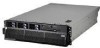
IBM 88743RU User Guide - Page 55
Microprocessor, installation, order
 |
UPC - 000435945938
View all IBM 88743RU manuals
Add to My Manuals
Save this manual to your list of manuals |
Page 55 highlights
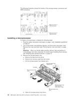
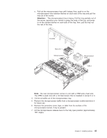
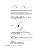
v Read the documentation that comes with the microprocessor to determine whether you must update the basic input/output system (BIOS) code in the server. To download the most current level of BIOS code for your server, see http://www.ibm.com/servers/eserver/support/xseries/index.html. v Obtain an SMP-capable operating system. For a list of supported operating systems, see http://www.ibm.com/servers/eserver/serverproven/compat/us/. v You can use the Configurations/Setup utility program to determine the specific type of microprocessor in the server. Microprocessor installation order The following notes describe the order in which to populate the microprocessor connectors: v For most configurations, populate the microprocessor connectors in numeric order, starting with connector 1. v If you plan to create a two-node configuration using four dual-core microprocessors, you can populate the microprocessor connectors to improve performance. The following notes describe information that you must consider when configuring the servers to use the configuration: - You must create this configuration using one System x3950 (xSeries 460) server as the primary node and one System x3950 E (xSeries 460 MXE) server as the secondary node. - Only the configuration described in these instructions is supported to improve performance. - See this section for instructions on installing a microprocessor. - See the Problem Determination and Service Guide for instructions on removing a microprocessor. - Use this configuration only with supported Windows 2003 operating systems. To configure a two-node configuration to use the four dual-core microprocessor configuration, complete the following steps. Important: The grease on the heat sink and microprocessor will remain effective when you move a microprocessor from one connector to another connector, if you observe the following precautions: v Carefully handle the heat sink and microprocessor when removing or installing these components. Do not touch the grease or otherwise allow it to become contaminated. v Because the microprocessor and heat sink are a matched set, transfer the microprocessor and heat sink from one connector to another connector one microprocessor and heat sink at a time. (This will ensure that the grease remains evenly distributed between each heat sink and microprocessor.) 1. Remove the microprocessor and heat sink installed in connector 2 of the primary node and install it in connector 1 of the secondary node. 2. Install a microprocessor and heat sink option in connector 3 of the primary node and install a VRM in VRM connector 3. 3. Install a microprocessor and heat sink option in connector 3 of the secondary node and install a VRM in VRM connector 3. Note: To install additional microprocessors in this configuration, populate connector 2; then, connector 4 in the primary node. To install additional microprocessors, populate connector 2; then, connector 4 in the secondary node. Chapter 2. Installing options 43
-
 1
1 -
2
-
3
-
4
-
5
-
6
-
7
-
8
-
9
-
10
-
11
-
12
-
13
-
14
-
15
-
16
-
17
-
18
-
19
-
20
-
21
-
22
-
23
-
24
-
25
-
26
-
27
-
28
-
29
-
30
-
31
-
32
-
33
-
34
-
35
-
36
-
37
-
38
-
39
-
40
-
41
-
42
-
43
-
44
-
45
-
46
-
47
-
48
-
49
-
 50
50 -
 51
51 -
 52
52 -
 53
53 -
 54
54 -
 55
55 -
 56
56 -
 57
57 -
 58
58 -
 59
59 -
 60
60 -
61
-
62
-
63
-
64
-
65
-
66
-
67
-
68
-
69
-
70
-
71
-
72
-
73
-
74
-
75
-
76
-
77
-
78
-
79
-
80
-
81
-
82
-
83
-
84
-
85
-
86
-
87
-
88
-
89
-
90
-
91
-
92
-
93
-
94
-
95
-
96
-
97
-
98
-
99
-
100
-
101
-
102
-
103
-
104
-
105
-
106
-
107
-
108
-
109
-
110
 |
 |
