Icom IC-A210 Instruction Manual
Icom IC-A210 Manual
 |
View all Icom IC-A210 manuals
Add to My Manuals
Save this manual to your list of manuals |
Icom IC-A210 manual content summary:
- Icom IC-A210 | Instruction Manual - Page 1
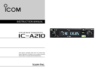
INSTRUCTION MANUAL VHF AIR BAND TRANSCEIVER iA210 This device complies with Part 15 of the FCC Rules. Operation is subject to the condition that this device does not cause harmful interference. - Icom IC-A210 | Instruction Manual - Page 2
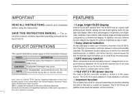
- struction manual contains important operating instructions for the IC-A210. light and display offers many advantages in brightness, not brightness, vividness, high contrast, wide viewing angle and response time compared to a conventional display. In addition, the auto dimmer function adjusts the - Icom IC-A210 | Instruction Manual - Page 3
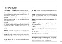
or modifications to this transceiver, not DO NOT place unit in a non-secure place to avoid inad- vertent use by children. expressly approved by Icom Inc., could void your authority to operate this transceiver under FCC regulations. ii - Icom IC-A210 | Instruction Manual - Page 4
19 I Accessing 121.5 MHz emergency frequency 19 I Intercom function 20 I Squelch test function 20 I Weather memory channel scan (U.S.A. version only 21 5 programming 22 I MENU mode items 23 6 INSTALLATION AND REMOVAL 28 I Transceiver installation 28 I Transceiver removal 28 7 CLONING 29 - Icom IC-A210 | Instruction Manual - Page 5
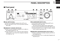
121.5 MHz) (p. 19). e VOLUME/POWER SWITCH [VOL] ➥ Turn [VOL] to switch the power ON and OFF (p. 5). ➥ Adjusts the audio output level. The volume level bar appears while rotating [VOL]. ➥ Push to set the squelch test function ON or OFF (p. 20). ➥ Push and hold for 2 sec. to start the weather channel - Icom IC-A210 | Instruction Manual - Page 6
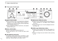
position (p. 15), etc. ➥ Rotate to change the scan direction while scanning u LIGHT-SENSITIVE DETECTOR (p. 21). This detector senses ambient light. The detector is used to adjust "Dimmer brightness (Low/High)" (p. 25) automat- ically when "Dimmer Mode" (p. 25) sets to 'AUTO.' 2 - Icom IC-A210 | Instruction Manual - Page 7
SPEAKER AND HEADPHONE JACK Connects a 13.8 V or 27.5 V DC power supply, speaker and headphone. Refer to the "INSTALLATION GUIDE" in details. q Metal catch (For Icom products) Use to attach to an installation rack for Icom products (p. 28). w Metal catch (For 3rd party products*) Use to attach to an - Icom IC-A210 | Instruction Manual - Page 8
Shows the selected memory channel number during mem- quency signal while dualwatch operation (p. 8). ➥ Appears when opening the active frequency's squelch function (p. 6). r INTERCOM INDICATOR Appears when the intercom function is in use (p. 20). ory mode (p. 13). !0 TEST INDICATOR Appears while - Icom IC-A210 | Instruction Manual - Page 9
2 BASIC OPERATION I Frequency selection IC-A210 has 2 ways to select the desired frequency. ï General frequency selection Select the desired frequency which is used for the next operating frequency in the standby - Icom IC-A210 | Instruction Manual - Page 10
Refer to pgs. 5-6 in details. • "RX" appears when receiving a signal or opening squelch. w Push [VOL] to open the squelch manually. • Refer to p. 20 "Squelch test function" in details. e Rotate the volume control to adjust the audio level. I Transmitting NOTE: To prevent interference, listen on the - Icom IC-A210 | Instruction Manual - Page 11
BASIC OPERATION 2 I Frequency set example The following example shows to how to select 126.40 MHz in the standby frequency indicator and then exchange it to the active 02 frequency indicator. RX 134.80 121.805 Previously used frequencies appear. q Rotate [O-DIAL] clockwise to select "126" MHz - Icom IC-A210 | Instruction Manual - Page 12
dualwatch operation. • "DUAL" appears on the active frequency indicator. • The active or standby frequency's "RX"blinks when receiving signal or opening the squelch. RX DUAL RX 121.00 129.405 w Push [DUAL] again to exit dualwatch operation. • "DUAL" disappears. • You may also exit dualwatch by - Icom IC-A210 | Instruction Manual - Page 13
is called as a blank channel. When a blank channel is selected while memory programming, "-----" appears instead of a frequency. ï Memory protect function IC-A210 has a memory protect function. The function prevents accidental changes or deletion. The function can be set in the MENU mode. I Entering - Icom IC-A210 | Instruction Manual - Page 14
3 MEMORY OPERATION I Channel selection The transceiver has 10 regular memory and 200 group channels (10 channels × 1 REGULAR MEMORY and 10 channels × 20 GROUPS) for storage of often-used frequencies along with 6-character notes. q Push [RCL] to enter the memory mode. • The channel number appears. - Icom IC-A210 | Instruction Manual - Page 15
MEMORY OPERATION 3 I Programming example The following is an example showing how to program 126.000 MHz into regular memory channel 4. q Set a "126.000 MHz" in the standby indicator. RX 134.80 126.005 "126.00" appears in the standby 03 indicator. w Push [RCL], then rotate [ODIAL] to select " - Icom IC-A210 | Instruction Manual - Page 16
3 MEMORY OPERATION I Transferring memory contents This function transfers a memory channel's contents into the active frequency indicator. q Push [RCL] to enter the memory mode. • The channel number appears. • The memory channel name also appears if it has been entered. w Rotate [O-DIAL] to select - Icom IC-A210 | Instruction Manual - Page 17
MEMORY OPERATION 3 I Regular memory channel The transceiver has 10 regular memory channels. 5 actions are selectable. q Push [RCL] to enter the memory mode. • The channel number appears. • The memory channel name also appears if it has been entered. w Rotate [O-DIAL] to select the regular memory - Icom IC-A210 | Instruction Manual - Page 18
3 MEMORY OPERATION I History memory channel The transceiver has 10 history memory channels. The standby frequency is stored into a history memory channel when pushing [↔]. The frequency is stored into the history memory channel in order from "CH01" to "CH10." q Push [RCL] to enter the memory mode. - Icom IC-A210 | Instruction Manual - Page 19
MEMORY OPERATION 3 I Programming channel names (Regular memory channel only) The regular memory channel can display a 6-character name in addition to the memory number. q Push [RCL], then rotate [O-DIAL] to select the desired regular memory channel in the memory mode. • Rotate [O-DIAL] to select - Icom IC-A210 | Instruction Manual - Page 20
YES Clearance / Delivery CTF YES YES Common Traffic Advisory Frequency DEP YES YES Departure Frequency FSS YES YES Flight Service Station RFS YES YES Remote Flight Service Station UNI YES YES Unicom frequency MF YES YES Mandatory frequency OTH YES - Other U-1 YES - User1 setting (Refer - Icom IC-A210 | Instruction Manual - Page 21
in the 03 GPS memory (maximum 10-memory channels). *Ask your dealer for available GPS receiver details. NOTE: See the GPS receiver's instruction manual when transferring the frequency data in details. q Push [RCL] to enter the memory mode. • The channel number appears. w Rotate [O-DIAL] to - Icom IC-A210 | Instruction Manual - Page 22
3 MEMORY OPERATION I GPS memory edit The received GPS memory data is stored to desired group memory channel. NOTE:The GPS memory data is overwritten if the setting group memory channel has already memorized other data. q Push [RCL] to enter the memory mode. • The channel number appears. • The - Icom IC-A210 | Instruction Manual - Page 23
when operating to push any keys (except [EC]) 8-times or rotating any dials (except [VOL]) 25clicks for 5 sec. I Accessing 121.5 MHz emergency frequency The IC-A210 can be set to the 121.5 MHz emergency fre- 03 quency quickly. This function can be activated even when the key lock function is in - Icom IC-A210 | Instruction Manual - Page 24
can be also selected "OFF" or "output level fixing (001-076)" in the MENU mode (p. 23). I Squelch test function This function opens the squelch manually for testing. q Push [VOL] to turn the squelch test function ON. • "TEST" appears. w To turn the function OFF, repeat step q as above. • "TEST - Icom IC-A210 | Instruction Manual - Page 25
I Weather memory channel scan (U.S.A. version only) Scanning searches for weather channel signals automatically and makes it easier to listen purposes. Repeatedly scans all weather memory channels. This function is available for the U.S.A. version only. q Set to the weather memory channel mode. w - Icom IC-A210 | Instruction Manual - Page 26
5 MENU MODE I MENU mode programming • MENU mode items MENU mode is available at power ON and allows you to set seldom-changed settings. In this way you can customize transceiver operations to suit your preferences and operating style. D Operating MENU mode q Rotate [VOL] to turn the transceiver - Icom IC-A210 | Instruction Manual - Page 27
the intercom2 microphone. • 001-076 : Setting the intercom2 input level from 1 to 80. . MENU MODE 5 D Intercom1 Squelch Level "MIC1 SQL" Set the intercom1 squelch level. The setting level is required to open the squelch when speak- ing to the intercom1. • OFF (0) : While opening the intercom1 - Icom IC-A210 | Instruction Manual - Page 28
signals properly, as well as for the scan to function effectively, the squelch must be adjusted to the proper level. • -010-010 : Setting AM squelch level from -10 to 10. D FM Squelch Level "FM SQL LV" (U.S.A. version only) Set the squelch level for FM mode operation. • -010-010 : Setting FM - Icom IC-A210 | Instruction Manual - Page 29
sensor which built-in the display is used for 05 this function. • MANUAL : Set the dimmer depending on Dimmer Brightness (Low) "DISP LOW". D (High) "DISP HIGH" Set the upper brightness level in the automatic adjustment range when "AUTO" is selected at the Dimmer Mode. • 050-100 : Setting - Icom IC-A210 | Instruction Manual - Page 30
D Dimmer Brightness (Manually) "DISP MAN." Set the brightness manually to suit your own preferences. • 0-100 : Setting dimmer level manually from 0 (OFF input does not use. • ON : The external input is available while squelch is closing. • INCOM : The external input is available with the intercom - Icom IC-A210 | Instruction Manual - Page 31
MENU MODE 5 I MENU mode items (Continued) D External Input Level "AUX LEVEL" Set the external input level. • OFF (0) : The external input does not operate. • 001-080 : Setting the external input level from 1 to 80. • AF GAIN : Interlocking with [VOL]. D Beep Tone Level "BEEP" Confirmation beep - Icom IC-A210 | Instruction Manual - Page 32
installation rack for 3rd party* products. ¥ Main unit front view Use for pre-existing Icom radio installations Use for pre-existing 3rd party radio* installations top/bottom view I Transceiver removal The IC-A210 may easily be removed from the installation rack, if desired. q Perform the same - Icom IC-A210 | Instruction Manual - Page 33
Data can be cloned to and from a PC (IBM compatible) using the optional CS-A210 CLONING SOFTWARE and the optional OPC1529R CLONING CABLE (connect with the data jack). Consult the CS-A210 instruction manual and HELP file for details. D Displayed Message • While clone writing. CLONE WRITE • When clone - Icom IC-A210 | Instruction Manual - Page 34
8 SPECIFICATIONS D General • Frequency range : 118.000 to 136.975 MHz 161.650 to 163.275 MHz* • Channel spacing : 25 kHz • Frequency stability : ±5 ppm • Operating temperature : -20˚C to +55˚C -4˚F to +131˚F • Antenna impedance : 50 Ω • Number of memory channels : 10 memory channels - Icom IC-A210 | Instruction Manual - Page 35
9 OPTIONS D CS-A210 CLONING SOFTWARE Provides quick and easy programming of items, including private channels, scan settings, etc., via an Windows® PC (Microsoft® Windows® 2000/Me/XP/Vista™) - Icom IC-A210 | Instruction Manual - Page 36
Dimmer brightness (High 25 Dimmer brightness (Low 25 Dimmer brightness (Manually 26 Dimmer mode 25 Dimmer response 26 Direct frequency selection 5 I Installation and removal 28 Intercom function 20 Intercom usable setting 27 Intercom1 Microphone audio input level 23 Intercom1 squelch level - Icom IC-A210 | Instruction Manual - Page 37
R Regular memory channel 9, 13 S Safety training information 35 Sidetone level 25 Squelch test function 20 Standby frequency selection 5 T Time-Out-Timer 27 Transceiver installation 28 Transceiver removal 28 Transferring memory contents 12 Transmitting 6 Transmitting microphone selection - Icom IC-A210 | Instruction Manual - Page 38
M E M O 34 - Icom IC-A210 | Instruction Manual - Page 39
separation distance. In order to ensure this distance is met, the installation of the antenna must be mounted at least 36 centimeters away from the radio to transmit by press- 10 ing the "PTT" switch. Electromagnetic Interference/Compatibility During transmissions, your Icom radio generates - Icom IC-A210 | Instruction Manual - Page 40
A-6602H-1EX Printed in Japan © 2007 Icom Inc. Printed on recycled paper with soy ink. 1-1-32 Kamiminami, Hirano-ku, Osaka 547-0003, Japan
-
 1
1 -
 2
2 -
 3
3 -
 4
4 -
 5
5 -
 6
6 -
 7
7 -
8
-
9
-
10
-
11
-
12
-
13
-
14
-
15
-
16
-
17
-
18
-
19
-
20
-
21
-
22
-
23
-
24
-
25
-
26
-
27
-
28
-
29
-
30
-
31
-
32
-
33
-
34
-
35
-
36
-
37
-
38
-
39
-
40
 |
 |
iA210
VHF AIR BAND TRANSCEIVER
INSTRUCTION MANUAL
This device complies with Part 15 of the FCC
Rules. Operation is subject to the condition that this
device does not cause harmful interference.