Icom IC-A210 Instruction Manual - Page 7
Rear panel, Main unit - installation
 |
View all Icom IC-A210 manuals
Add to My Manuals
Save this manual to your list of manuals |
Page 7 highlights
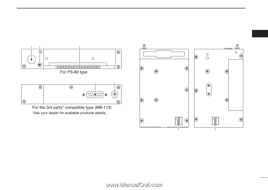
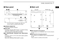
I Rear panel qw e PANEL DESCRIPTION 1 I Main unit 01 • Top view • Bottom view For PS-80 type e q For the 3rd party* compatible type (MB-113) *Ask your dealer for available products details. q ANTENNA CONNECTOR Connects an antenna connector. w DATA JACK q w Connects a 3rd party GPS receiver*1 or optional cloning cable (OPC-1529R). Refer to p.29 for details. *1Ask your dealer for available GPS receiver details. e DC, MICROPHONE, SPEAKER AND HEADPHONE JACK Connects a 13.8 V or 27.5 V DC power supply, speaker and headphone. Refer to the "INSTALLATION GUIDE" in details. q Metal catch (For Icom products) Use to attach to an installation rack for Icom products (p. 28). w Metal catch (For 3rd party products*) Use to attach to an installation rack for 3rd party products* (p. 28). *Ask your dealer for available products details. 3
-
 1
1 -
 2
2 -
 3
3 -
 4
4 -
 5
5 -
 6
6 -
 7
7 -
 8
8 -
 9
9 -
 10
10 -
 11
11 -
 12
12 -
13
-
14
-
15
-
16
-
17
-
18
-
19
-
20
-
21
-
22
-
23
-
24
-
25
-
26
-
27
-
28
-
29
-
30
-
31
-
32
-
33
-
34
-
35
-
36
-
37
-
38
-
39
-
40
 |
 |