Icom IC-A210 Instruction Manual - Page 8
Function display - squelch
 |
View all Icom IC-A210 manuals
Add to My Manuals
Save this manual to your list of manuals |
Page 8 highlights
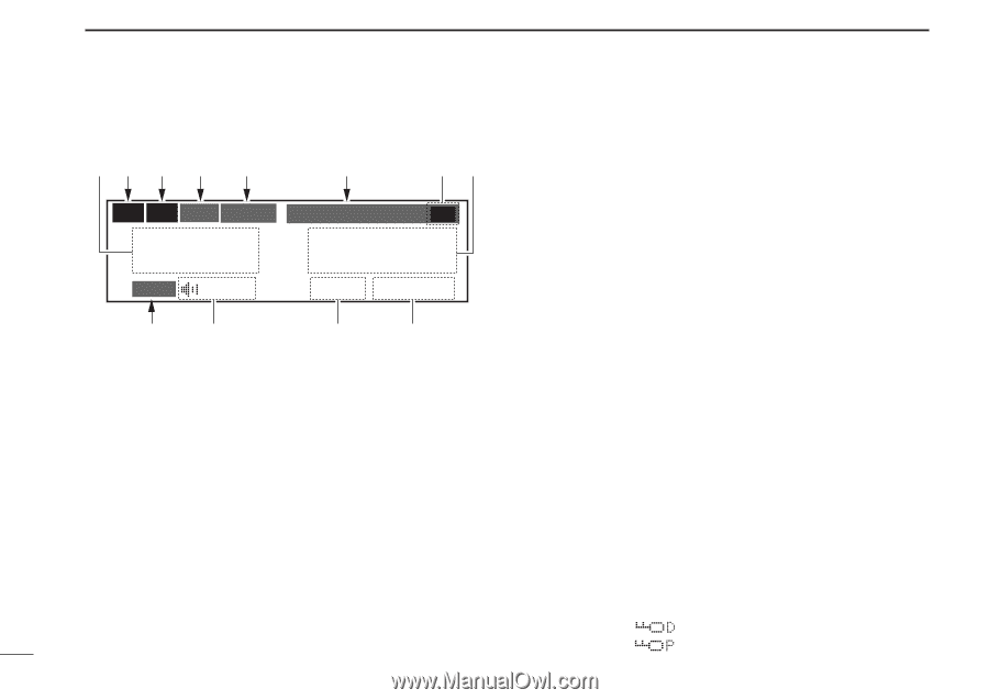
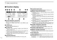
1 PANEL DESCRIPTION I Function display qw e r t t DUALWATCH INDICATOR y eu Appears when the dualwatch function is active (p. 8). TX RX ICS DUAL MEMORY RX y MEMORY CONDITION INDICATOR ➥ Indicates "MEMORY" when the regular memory channel 118.00 121.525 is selected (p. 13). ➥ Indicates "GRP01-GRP20" when the group memory channel is selected (p. 13). F O D TEST CH09 SAMPLE !1 !0 o i q ACTIVE FREQUENCY INDICATOR ➥ Shows the active frequency (p. 6). ➥Shows the MENU mode items in the MENU mode (p. 22). w TX INDICATOR Appears while transmitting (p. 6). e RX INDICATOR ➥ Appears when receiving a signal on the active fre- The group name is also indicated if the name has been entered. ➥ Indicates "HISTORY" when the history memory chan- nel is selected (p. 14). ➥ Indicates "WEATHER" when the weather memory chan- nel is selected (U.S.A. version only) (p. 17). ➥ Indicates "GPS" when the GPS memory channel is se- lected (The 3rd party GPS receiver is required) (p. 17). u STANDBY FREQUENCY INDICATOR ➥ Shows the standby frequency (p. 5). ➥ Shows the setting values in the MENU mode (p. 22). i CHANNEL NAME INDICATOR Shows the channel name during memory mode (p. 15). quency signal (p. 6). o MEMORY CHANNEL INDICATOR ➥ Appears when receiving a signal on the standby fre- Shows the selected memory channel number during mem- quency signal while dualwatch operation (p. 8). ➥ Appears when opening the active frequency's squelch function (p. 6). r INTERCOM INDICATOR Appears when the intercom function is in use (p. 20). ory mode (p. 13). !0 TEST INDICATOR Appears while the squelch test function is active (p. 20). !1 LOCK INDICATOR (p. 19) ➥ Indicates " " while the dial lock function is in use. ➥ Indicates " " while the panel lock function in use. 4
-
 1
1 -
2
-
 3
3 -
 4
4 -
 5
5 -
 6
6 -
 7
7 -
 8
8 -
 9
9 -
 10
10 -
 11
11 -
 12
12 -
 13
13 -
14
-
15
-
16
-
17
-
18
-
19
-
20
-
21
-
22
-
23
-
24
-
25
-
26
-
27
-
28
-
29
-
30
-
31
-
32
-
33
-
34
-
35
-
36
-
37
-
38
-
39
-
40
 |
 |