Icom IC-A210 Instruction Manual - Page 32
Installation And Removal - radio
 |
View all Icom IC-A210 manuals
Add to My Manuals
Save this manual to your list of manuals |
Page 32 highlights
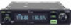
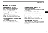
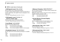
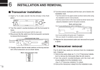
6 INSTALLATION AND REMOVAL I Transceiver installation q Insert a 3/32 in allen wrench into the 2-holes in the front panel. DUAL EC VOL RCL MEM COMM OFF PUSH TEST iA210 w Turn the wrench counterclockwise until the front panel is loose. • A cable connects the front panel with the main unit. e Disconnect the flat cable from the front panel's connector to remove the front panel. • Front panel rear view Disconnect from here. t Turn the wrench clockwise until the main unit is fixed to the installation rack. • Turn the wrench in the upper socket as shown below when using the installation rack for Icom products. • Turn the wrench when in the lower socket as shown below when using the installation rack for 3rd party* products. ¥ Main unit front view Use for pre-existing Icom radio installations Use for pre-existing 3rd party radio* installations *Ask your dealer for available products details. y Replace the disconnected cable and removed front panel in place. r Visually confirm that the metal catches on the top and bottom of the transceiver are as shown below. • Main unit top/bottom view I Transceiver removal The IC-A210 may easily be removed from the installation rack, if desired. q Perform the same steps as q-e of "Transceiver installa- tion" to remove the front panel (See the left column). w Turn the wrench counterclockwise until the main unit moves slightly from the installation rack. • See t of "Transceiver installation" for details. e Pull out the transceiver slowly from the installation rack. 28
-
 1
1 -
2
-
3
-
4
-
5
-
6
-
7
-
8
-
9
-
10
-
11
-
12
-
13
-
14
-
15
-
16
-
17
-
18
-
19
-
20
-
21
-
22
-
23
-
24
-
25
-
26
-
 27
27 -
 28
28 -
 29
29 -
 30
30 -
 31
31 -
 32
32 -
 33
33 -
 34
34 -
 35
35 -
 36
36 -
 37
37 -
38
-
39
-
40
 |
 |