Intel BX80580Q9400 User Manual - Page 10
Glossary of Terms and Acronyms - specifications
 |
UPC - 735858203074
View all Intel BX80580Q9400 manuals
Add to My Manuals
Save this manual to your list of manuals |
Page 10 highlights
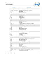
About This Manual Notation V µA µF µs µW Signal Names Definition volts microamps, microamperes microfarads microseconds microwatts Signal names are shown in uppercase. When several signals share a common name, an individual signal is represented by the signal name followed by a number, while the group is represented by the signal name followed by a variable (n). For example, the lower chip-select signals are named CS0#, CS1#, CS2#, and so on; they are collectively called CSn#. A pound symbol (#) appended to a signal name identifies an active-low signal. Port pins are represented by the port abbreviation, a period, and the pin number (e.g., P1.0). 1.3 Glossary of Terms and Acronyms Table 2 defines terms used in this document. Table 2. Definitions of Terms Term/Acronym Definition Assisted Gunning Transceiver Logic+ Asynchronous GTL+ Fern Hill Infrared Data Assoc. IMVP6+ The front-side bus uses a bus technology called AGTL+, or Assisted Gunning Transceiver Logic. AGTL+ buffers are open-drain, and require pull-up resistors to provide the high logic level and termination. AGTL+ output buffers differ from GTL+ buffers with the addition of an active pMOS pull-up transistor to assist the pull-up resistors during the first clock of a low-to-high voltage transition. The processor does not utilize CMOS voltage levels on any signals that connect to the processor. As a result, legacy input signals such as A20M#, IGNNE#, INIT#, LINT0/INTR, LINT1/NMI, PWRGOOD, SMI#, SLP#, and STPCLK# utilize GTL+ input buffers. Legacy output signals (FERR# and IERR#) and non-AGTL+ signals (THERMTRIP# and PROCHOT#) also utilize GTL+ output buffers. All of these signals follow the same DC requirements as AGTL+ signals, however the outputs are not actively driven high (during a logical 0 to 1 transition) by the processor (the major difference between GTL+ and AGTL+). These signals do not have setup or hold time specifications in relation to BCLK[1:0], and are therefore referred to as "Asynchronous GTL+ Signals". However, all of the Asynchronous GTL+ signals are required to be asserted for at least two BCLKs in order for the processor to recognize them. The name of the development board that uses Intel® Core™ 2 Duo processor SU9400 or SL9400 with the Mobile Intel GS45 Express Chipset (Small Form Factor) and DDR3 SDRAM The Infrared Data Association (IrDA) has outlined a specification for serial communication between two devices via a bi-directional infrared data port. The development board has such a port and it is located on the rear of the board between the two USB connectors. The Intel Mobile Voltage Positioning specification for the Intel® Core™ 2 Duo Processor. It is a DC-DC converter module that supplies the required voltage and current to a single processor. 10 Development Kit User's Manual
-
 1
1 -
2
-
3
-
4
-
 5
5 -
 6
6 -
 7
7 -
 8
8 -
 9
9 -
 10
10 -
 11
11 -
 12
12 -
 13
13 -
 14
14 -
 15
15 -
16
-
17
-
18
-
19
-
20
-
21
-
22
-
23
-
24
-
25
-
26
-
27
-
28
-
29
-
30
-
31
-
32
-
33
-
34
-
35
-
36
-
37
-
38
-
39
-
40
-
41
-
42
-
43
-
44
-
45
-
46
-
47
-
48
-
49
-
50
-
51
-
52
-
53
-
54
-
55
-
56
-
57
-
58
-
59
-
60
-
61
-
62
-
63
-
64
-
65
-
66
-
67
-
68
-
69
-
70
-
71
-
72
-
73
-
74
-
75
-
76
-
77
-
78
-
79
-
80
-
81
-
82
-
83
-
84
 |
 |
