Intel S1200BT Technical Product Specification - Page 135
Power Supply Output Requirements
 |
View all Intel S1200BT manuals
Add to My Manuals
Save this manual to your list of manuals |
Page 135 highlights
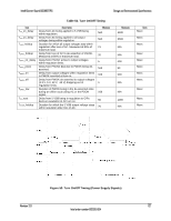
Intel® Server Board S1200BT TPS Design and Environmental Specifications 10.2.1 Processor Power Support The server board supports the Thermal Design Power (TDP) guideline for Intel® Xeon® processor. The Flexible Motherboard Guidelines (FMB) was also followed to help determine the suggested thermal and current design values for anticipating future processor needs. The following table provides maximum values for Icc, TDP power and TCASE for the Intel® Xeon® SandyBridge Series processor. Table 47. Intel® Xeon® Processor TDP Guidelines TDP Power 95 W Maximum TCASE 67.0ºC Icc Maximum 150 A 10.3 Power Supply Output Requirements This section is for reference purposes only. The intent is to provide guidance to system designers to determine a power supply for use with this server board. This section specifies the power supply requirements Intel® used to develop a power supply for the Intel® Server System R1304BTLSHBN. The following tables define two power and current ratings for this 350-W power supply. The combined output power of all outputs should not exceed the rated output power. The power supply must meet both static and dynamic voltage regulation requirements for the minimum loading conditions. Table 48. 350-W Load Ratings Voltage Minimum Continuous Maximum Continuous Peak +3.3 V 0.2A 14 A +5 V 1.0 A 18A +12 V 1.5A 24 A 28A -12 V 0A 0.3A +5 VSB 0.1 A 2.0 A 2.5 A Notes: 1. Maximum continuous total DC output power should not exceed 350 W. 2. Peak total DC output power should not exceed 400 W. 3. Peak power and peak current loading should be supported for a minimum of 12 seconds. 4. Combined 3.3 V/5 V power should not exceed 100 W. Revision 2.0 123 Intel order number G13326-004
-
 1
1 -
2
-
3
-
4
-
5
-
6
-
7
-
8
-
9
-
10
-
11
-
12
-
13
-
14
-
15
-
16
-
17
-
18
-
19
-
20
-
21
-
22
-
23
-
24
-
25
-
26
-
27
-
28
-
29
-
30
-
31
-
32
-
33
-
34
-
35
-
36
-
37
-
38
-
39
-
40
-
41
-
42
-
43
-
44
-
45
-
46
-
47
-
48
-
49
-
50
-
51
-
52
-
53
-
54
-
55
-
56
-
57
-
58
-
59
-
60
-
61
-
62
-
63
-
64
-
65
-
66
-
67
-
68
-
69
-
70
-
71
-
72
-
73
-
74
-
75
-
76
-
77
-
78
-
79
-
80
-
81
-
82
-
83
-
84
-
85
-
86
-
87
-
88
-
89
-
90
-
91
-
92
-
93
-
94
-
95
-
96
-
97
-
98
-
99
-
100
-
101
-
102
-
103
-
104
-
105
-
106
-
107
-
108
-
109
-
110
-
111
-
112
-
113
-
114
-
115
-
116
-
117
-
118
-
119
-
120
-
121
-
122
-
123
-
124
-
125
-
126
-
127
-
128
-
129
-
 130
130 -
 131
131 -
 132
132 -
 133
133 -
 134
134 -
 135
135 -
 136
136 -
 137
137 -
 138
138 -
 139
139 -
 140
140 -
141
-
142
-
143
-
144
-
145
-
146
-
147
-
148
-
149
-
150
-
151
-
152
-
153
-
154
-
155
-
156
-
157
-
158
-
159
-
160
-
161
-
162
-
163
-
164
 |
 |
