Intel S1200BT Technical Product Specification - Page 136
Grounding, Standby Outputs, Remote Sense, Voltage Regulation, Dynamic Loading
 |
View all Intel S1200BT manuals
Add to My Manuals
Save this manual to your list of manuals |
Page 136 highlights
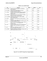
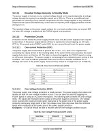
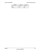
Design and Environmental Specifications Intel® Server Board S1200BT TPS 10.3.1 Grounding The grounds of the power supply output connector pins provide the power return path. The output connector ground pins are connected to the safety ground (power supply enclosure). This grounding is designed to ensure passing the maximum allowed common mode noise levels. The power supply is provided with a reliable protective earth ground. All secondary circuits are connected to protective earth ground. Resistance of the ground returns to chassis does not exceed 1.0 m. This path may be used to carry DC current. 10.3.2 Standby Outputs The 5 VSB output is present when an AC input greater than the power supply turn on voltage is applied. 10.3.3 Remote Sense The power supply has remote sense return (ReturnS) to regulate out ground drops for all output voltages: +3.3 V, +5 V, +12 V, -12 V, and 5 VSB. The power supply uses remote sense to regulate out drops in the system for the +3.3 V, +5 V, and 12 V outputs. The power supply must operate within specification over the full range of voltage drops from the power supply's output connector to the remote sense points. 10.3.4 Voltage Regulation The power supply output voltages must stay within the following voltage limits when operating at steady state and dynamic loading conditions. These limits include the peak-peak ripple/noise. All outputs are measured with reference to the return remote sense signal (ReturnS). Table 49. Voltage Regulation Limits Parameter + 3.3 V + 5 V + 12 V - 12 V + 5 VSB Tolerance - 5% / +5% - 5% / +5% - 5% / +5% - 10% / +10% - 5% / +5% Minimum +3.14 +4.75 +11.40 -13.20 +4.75 Normal +3.30 +5.00 +12.00 -12.00 +5.00 Maximum +3.46 +5.25 +12.60 -10.80 +5.25 Units Vrms Vrms Vrms Vrms Vrms 10.3.5 Dynamic Loading The output voltages remain within limits for the step loading and capacitive loading specified in the following table. The load transient repetition rate is tested between 50 Hz and 5 kHz at duty cycles ranging from 10%-90%. The load transient repetition rate is only a test specification. The step load may occur anywhere within the Min load to the Max load conditions. Output +3.3 V +5 V 12 V 124 Table 50. Transient Load Requirements ∆ Step Load Size (See note 2) 5.0 A 6.0 A 11.0 A Load Slew Rate 0.25 A/µsec 0.25 A/µsec 0.25 A/µsec Test capacitive Load 250 µF 400 µF 500 µF Intel order number G13326-004 Revision 2.0
-
 1
1 -
2
-
3
-
4
-
5
-
6
-
7
-
8
-
9
-
10
-
11
-
12
-
13
-
14
-
15
-
16
-
17
-
18
-
19
-
20
-
21
-
22
-
23
-
24
-
25
-
26
-
27
-
28
-
29
-
30
-
31
-
32
-
33
-
34
-
35
-
36
-
37
-
38
-
39
-
40
-
41
-
42
-
43
-
44
-
45
-
46
-
47
-
48
-
49
-
50
-
51
-
52
-
53
-
54
-
55
-
56
-
57
-
58
-
59
-
60
-
61
-
62
-
63
-
64
-
65
-
66
-
67
-
68
-
69
-
70
-
71
-
72
-
73
-
74
-
75
-
76
-
77
-
78
-
79
-
80
-
81
-
82
-
83
-
84
-
85
-
86
-
87
-
88
-
89
-
90
-
91
-
92
-
93
-
94
-
95
-
96
-
97
-
98
-
99
-
100
-
101
-
102
-
103
-
104
-
105
-
106
-
107
-
108
-
109
-
110
-
111
-
112
-
113
-
114
-
115
-
116
-
117
-
118
-
119
-
120
-
121
-
122
-
123
-
124
-
125
-
126
-
127
-
128
-
129
-
130
-
 131
131 -
 132
132 -
 133
133 -
 134
134 -
 135
135 -
 136
136 -
 137
137 -
 138
138 -
 139
139 -
 140
140 -
 141
141 -
142
-
143
-
144
-
145
-
146
-
147
-
148
-
149
-
150
-
151
-
152
-
153
-
154
-
155
-
156
-
157
-
158
-
159
-
160
-
161
-
162
-
163
-
164
 |
 |
