Invacare 9XT Owners Manual - Page 66
Adjusting Patient-Operated Wheel Locks, Push-To-Lock, Pull-To-Lock, Unlocked, Position, Unlocked
 |
View all Invacare 9XT manuals
Add to My Manuals
Save this manual to your list of manuals |
Page 66 highlights
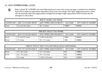
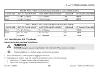
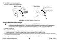
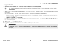
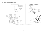
10 ANTI-TIPPERS/WHEEL LOCKS 3. Disengage the wheel locks by reversing STEP 2. Push-To-Lock Wheel Lock Unlocked Position Locked Position Pull-To-Lock Wheel Lock Locked Position Unlocked Position FIGURE 3 Using Patient Operated Disk Wheel Locks Adjusting Patient-Operated Wheel Locks The push-or-pull-to-lock wheel locks are also an option on the 9000XT Recliner. If wheels are pneumatic, before adjusting or replacing the wheel lock assemblies, ensure that the tires are inflated to the recommended psi on the side wall of tire. The recommended tire pressure is located on the side wall of the tire. 1. Disengage the wheel locks. 2. Perform one of the following: • Bolt-on Wheel locks - Loosen the bolt and locknut that secure the wheel lock to the wheelchair frame. • Clamp-on wheel locks - Loosen the two socket screws that secure the wheel lock to the wheelchair frame. 3. Reposition the wheel lock so that when engaged, the wheel lock shoe embeds the tire 1/8-inch (3/16-inch for pneumatic tires) and holds the occupied wheelchair in place when pushed. 4. Securely tighten the bolt and locknut or socket screws securing the wheel lock to the wheelchair frame. Invacare® 9000 Series Wheelchair 66 Part No. 1056953
-
 1
1 -
2
-
3
-
4
-
5
-
6
-
7
-
8
-
9
-
10
-
11
-
12
-
13
-
14
-
15
-
16
-
17
-
18
-
19
-
20
-
21
-
22
-
23
-
24
-
25
-
26
-
27
-
28
-
29
-
30
-
31
-
32
-
33
-
34
-
35
-
36
-
37
-
38
-
39
-
40
-
41
-
42
-
43
-
44
-
45
-
46
-
47
-
48
-
49
-
50
-
51
-
52
-
53
-
54
-
55
-
56
-
57
-
58
-
59
-
60
-
 61
61 -
 62
62 -
 63
63 -
 64
64 -
 65
65 -
 66
66 -
 67
67 -
 68
68 -
 69
69 -
 70
70 -
 71
71 -
72
-
73
-
74
-
75
-
76
-
77
-
78
-
79
-
80
-
81
-
82
-
83
-
84
-
85
-
86
-
87
-
88
-
89
-
90
-
91
-
92
 |
 |
