Invacare 9XT Owners Manual - Page 81
Installing Telescoping I.V. Rod, Installing I.V. Holder, DETAIL A, DETAIL B
 |
View all Invacare 9XT manuals
Add to My Manuals
Save this manual to your list of manuals |
Page 81 highlights
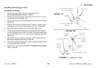
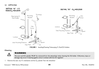
Installing Telescoping I.V. Rod Installing I.V. Holder 1. Remove the rear wheel from the wheelchair. Refer to Removing/Installing Rear Wheels on page 77. 2. Remove the locknut and hex screw that secure the arm socket to the wheelchair frame (Detail "A"). 3. Remove the locknut that secures the back tube to the clevis bracket (Detail "B). 4. Position the top hole on the flat portion of the I.V. holder on the existing pivot screw of the clevis bracket as shown in Detail "B". 5. Reinstall locknut onto pivot screw. DO NOT tighten yet. 6. Thread the provided mounting screw through the lower hole on the front cylinder section of the I.V. holder, through the side frame, and into the locknut. Turn nut until snug fit is obtained. DO NOT tighten yet. 7. Reinstall the arm to orient front cylinder of I.V. holder. Refer to Removing or Replacing Armrest on page 48. 8. Once front cylinder is oriented for proper clearance of the armrest, securely tighten both locknuts. 9. Install the I. V. rod support tube. Refer to Installing I.V. Rod Support Tube on page 82. Arm Socket (Outside of Wheelchair Frame) DETAIL "A" Locknut 11 RECLINER Hex Screw Outside of Wheelchair Frame DETAIL "B" Locknut (STEP 6) Back Tube (STEP 3) I.V. Holder (STEP 4) Clevis Bracket (STEP 3) Mounting Screw (STEP 6) Pivot Screw (STEP 4) Locknut (STEPS 3 and 5) FIGURE 12 Installing I.V. Holder Part No. 1056953 81 Invacare® 9000 Series Wheelchair
-
 1
1 -
2
-
3
-
4
-
5
-
6
-
7
-
8
-
9
-
10
-
11
-
12
-
13
-
14
-
15
-
16
-
17
-
18
-
19
-
20
-
21
-
22
-
23
-
24
-
25
-
26
-
27
-
28
-
29
-
30
-
31
-
32
-
33
-
34
-
35
-
36
-
37
-
38
-
39
-
40
-
41
-
42
-
43
-
44
-
45
-
46
-
47
-
48
-
49
-
50
-
51
-
52
-
53
-
54
-
55
-
56
-
57
-
58
-
59
-
60
-
61
-
62
-
63
-
64
-
65
-
66
-
67
-
68
-
69
-
70
-
71
-
72
-
73
-
74
-
75
-
 76
76 -
 77
77 -
 78
78 -
 79
79 -
 80
80 -
 81
81 -
 82
82 -
 83
83 -
 84
84 -
 85
85 -
 86
86 -
87
-
88
-
89
-
90
-
91
-
92
 |
 |
