Lantronix Spider Lantronix Spider / SpiderDuo - User Guide - Page 35
Serial Ports, Optional Auxiliary DC Power Supply Redundancy, Ethernet Ports, Local KVM Port
 |
View all Lantronix Spider manuals
Add to My Manuals
Save this manual to your list of manuals |
Page 35 highlights
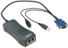
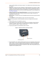
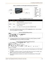
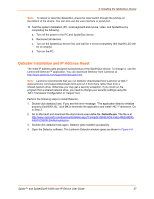
4: Installing the SpiderDuo Device cases, the PS/2-interface model may be required. You configure either interface type by using the software. Serial Ports-Performs the initial configuration to setup parameters and connects to a target COM port. It also allows remote users to Telnet or SSH to that port, eliminating the need for a separate box to perform serial command line management. The serial port can also connect to the Power Control Unit (PCU) for use as an AC power passthrough. For more information, see PCU Power on page 43. Optional Auxiliary DC Power Supply (Redundancy)-Overcomes the loss of power when the attached server goes down by using the auxiliary DC power supply connected to an independent AC power source. Ethernet Ports-Connects to the LAN. The SpiderDuo device has one port only that connects to the LAN. Local KVM Port-Connects keyboard, video, and mouse to the local client. Perform the following steps to install the SpiderDuo device and configure the initial network settings. 1. Plug the RJ45 cable into the SpiderDuo serial port. 2. Plug the DB9F end of the RJ45 cable into the COM port of a PC/laptop running a terminal emulator, for example HyperTerminal. The default serial port settings are: 9600 bits per second, 8 data bits, no parity, 1 stop bit, no flow control. 3. Plug the power adaptor into the SpiderDuo power connector. Figure 4-1 SpiderDuo RJ45 Port and Power Connector RJ45 Ethernet Port Power Connector 4. Plug the SpiderDuo video, USB, and PS/2 keyboard and mouse (if applicable) cables into the target computer. The blue LED SysOK lluminates and flashes to indicate that the SpiderDuo device is booting up. Bootup completes within approximately one minute. The SysOK LED stops flashing and remains illuminated. Connections for video, USB, and keyboard/mouse are integrated into the SpiderDuo device. Spider™ and SpiderDuo® KVM-over-IP Device User Guide 35
-
 1
1 -
2
-
3
-
4
-
5
-
6
-
7
-
8
-
9
-
10
-
11
-
12
-
13
-
14
-
15
-
16
-
17
-
18
-
19
-
20
-
21
-
22
-
23
-
24
-
25
-
26
-
27
-
28
-
29
-
 30
30 -
 31
31 -
 32
32 -
 33
33 -
 34
34 -
 35
35 -
 36
36 -
 37
37 -
 38
38 -
 39
39 -
 40
40 -
41
-
42
-
43
-
44
-
45
-
46
-
47
-
48
-
49
-
50
-
51
-
52
-
53
-
54
-
55
-
56
-
57
-
58
-
59
-
60
-
61
-
62
-
63
-
64
-
65
-
66
-
67
-
68
-
69
-
70
-
71
-
72
-
73
-
74
-
75
-
76
-
77
-
78
-
79
-
80
-
81
-
82
-
83
-
84
-
85
-
86
-
87
-
88
-
89
-
90
-
91
-
92
-
93
-
94
-
95
-
96
-
97
-
98
-
99
-
100
-
101
-
102
-
103
-
104
-
105
-
106
-
107
-
108
-
109
-
110
-
111
-
112
-
113
-
114
-
115
-
116
-
117
-
118
-
119
-
120
-
121
-
122
-
123
-
124
-
125
-
126
-
127
-
128
-
129
-
130
-
131
-
132
-
133
 |
 |
