Lantronix Spider Lantronix Spider / SpiderDuo - User Guide - Page 43
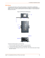
PCU Power, Blue LED = Sys OK.
 |
View all Lantronix Spider manuals
Add to My Manuals
Save this manual to your list of manuals |
Page 43 highlights
4: Installing the SpiderDuo Device PCU Power To remotely control power to a PC and other equipment, an optional PCU is available (part number PCU100-01). The PCU manages power remotely to a target PC and other equipment. In addition, the user can restart or power-cycle the PC and other equipment. shows the layout and dimensions of the PCU. Figure 4-10 PCU Layout and Dimensions Complete the following tasks to connect the PCU. 1. Connect the power output plug to a target PC or other equipment. 2. Connect the RJ45 cable from the PCU to the SpiderDuo serial port. 3. Connect the power input plug to AC power. Green LED = PCU ON (AC power pass- through), Blue LED = Sys OK. Spider™ and SpiderDuo® KVM-over-IP Device User Guide 43
-
 1
1 -
2
-
3
-
4
-
5
-
6
-
7
-
8
-
9
-
10
-
11
-
12
-
13
-
14
-
15
-
16
-
17
-
18
-
19
-
20
-
21
-
22
-
23
-
24
-
25
-
26
-
27
-
28
-
29
-
30
-
31
-
32
-
33
-
34
-
35
-
36
-
37
-
 38
38 -
 39
39 -
 40
40 -
 41
41 -
 42
42 -
 43
43 -
 44
44 -
 45
45 -
 46
46 -
 47
47 -
 48
48 -
49
-
50
-
51
-
52
-
53
-
54
-
55
-
56
-
57
-
58
-
59
-
60
-
61
-
62
-
63
-
64
-
65
-
66
-
67
-
68
-
69
-
70
-
71
-
72
-
73
-
74
-
75
-
76
-
77
-
78
-
79
-
80
-
81
-
82
-
83
-
84
-
85
-
86
-
87
-
88
-
89
-
90
-
91
-
92
-
93
-
94
-
95
-
96
-
97
-
98
-
99
-
100
-
101
-
102
-
103
-
104
-
105
-
106
-
107
-
108
-
109
-
110
-
111
-
112
-
113
-
114
-
115
-
116
-
117
-
118
-
119
-
120
-
121
-
122
-
123
-
124
-
125
-
126
-
127
-
128
-
129
-
130
-
131
-
132
-
133
 |
 |

4: Installing the SpiderDuo Device
Spider™ and SpiderDuo® KVM-over-IP Device User Guide
43
PCU Power
To remotely control power to a PC and other equipment, an optional PCU is available (part
number PCU100-01). The PCU manages power remotely to a target PC and other equipment. In
addition, the user can restart or power-cycle the PC and other equipment.
shows the layout and
dimensions of the PCU.
Figure 4-10
PCU Layout and Dimensions
Complete the following tasks to connect the PCU.
1.
Connect the power output plug to a target PC or other equipment.
2.
Connect the RJ45 cable from the PCU to the SpiderDuo serial port.
3.
Connect the power input plug to AC power. Green LED = PCU ON (AC power pass- through),
Blue LED = Sys OK.