Lantronix xPico xPico - Integration Guide
Lantronix xPico Manual
 |
View all Lantronix xPico manuals
Add to My Manuals
Save this manual to your list of manuals |
Lantronix xPico manual content summary:
- Lantronix xPico | xPico - Integration Guide - Page 1
xPico Embedded Device Server Integration Guide Part Number 900-619 Revision G February 2014 - Lantronix xPico | xPico - Integration Guide - Page 2
Wi-Fi is a registered trademark of Wi-Fi Alliance. Ethertronics is a registered trademark of Ethertronics. All other trademarks and trade names are the property of their respective holders. Contacts Lantronix with the instructions, may cause xPico® Embedded Device Server Integration Guide 2 - Lantronix xPico | xPico - Integration Guide - Page 3
(xPico Wi-Fi only) The label on the end product incorporating the xPico Wi-Fi module must clearly state that it contains an FCC-approved RF module. Lantronix will void the user's authority to operate this device. Note: With the purchase of any xPico family product, the OEM agrees to an OEM firmware - Lantronix xPico | xPico - Integration Guide - Page 4
Wi-Fi part information. Updated to include Japanese certification number. Updated reference schematic information. Updated for firmware version 1.1.0.2R10. For the latest revision of this product document, please check our online documentation at www.lantronix.com/support/documentation. xPico - Lantronix xPico | xPico - Integration Guide - Page 5
Serial Interface 23 USB Device Port (xPico Wi-Fi only 25 LEDs 26 General Purpose I/O Pins 27 Reset Pins 27 Evaluation Board Schematics 28 3. Mounting Instructions and PCB Footprint 33 To Access CAD Files 33 To Install the xPico or xPico Wi-Fi Module 34 Product Information Label 37 - Lantronix xPico | xPico - Integration Guide - Page 6
Mounting Instructions for PEM Standoff 36 Figure 3-4 Hirose Connector Layout 37 Figure 3-5 xPico Product Label 37 Figure 3-6 xPico Wi-Fi Product Label 38 List of Tables Table 1-1 xPico and xPico Wi-Fi Features 8 Table 2-1 xPico Part Numbers 10 Table 2-2 xPico and xPico Wi-Fi Pin Connections - Lantronix xPico | xPico - Integration Guide - Page 7
39 Table 4-3 xPico WiFi Recommended Operating Conditions 40 Table 4-4 xPico Wired Technical Specification 41 Table 4-5 xPico Wi-Fi Technical Specification 41 B-4 Europe - EU Declaration of Conformity 46 Table B-5 Approved Antenna(s) List 51 xPico® Embedded Device Server Integration Guide 7 - Lantronix xPico | xPico - Integration Guide - Page 8
, and update the xPico firmware. xPico Wi-Fi Embedded Provides information needed to configure, use, and Device Server User Guide update the xPico Wi-Fi firmware. xPico Embedded Device Server Development Kit Provides the steps for getting the xPico up and running. xPico® Embedded Device Server - Lantronix xPico | xPico - Integration Guide - Page 9
the IAP device server using our Modbus firmware. Provides instructions for using the Windows-based utility to configure the xPico and other Lantronix device servers. Provides information on using the Windows-based utility to create a virtual com port. Provides guidance in developing a manufacturing - Lantronix xPico | xPico - Integration Guide - Page 10
Wi-Fi - IEEE 802.11 b/g/n Device Server Development Kit w/ Module, RoHS XPC10010MB-01 xPico IAP Device Server Module, Extended Temperature, Modbus, RoHS, Bulk XPC10010MS-01 xPico IAP Device Server Module, Extended Temperature, Modbus, RoHS, Sample xPico® Embedded Device Server Integration Guide - Lantronix xPico | xPico - Integration Guide - Page 11
external Ethernet magnetic module and RJ45 Jack is required to interface to a standard 10/100Mbps Ethernet network. The xPico requires +3.3-volt power and is designed to operate in an extended temperature range (see technical data). xPico Wi-Fi Features The xPico Wi-Fi device server contains Cortex - Lantronix xPico | xPico - Integration Guide - Page 12
2: Functional Description Figure 2-1 xPico and xPico Wi-Fi Dimensions and Views xPico® Embedded Device Server Integration Guide 12 - Lantronix xPico | xPico - Integration Guide - Page 13
2: Functional Description xPico Block Diagram The following drawing is a block diagram of the xPico embedded device server showing the relationships of the components. Figure 2-2 xPico Block Diagram xPico® Embedded Device Server Integration Guide 13 - Lantronix xPico | xPico - Integration Guide - Page 14
of the components. 40 Pin Connector Interface DC Power 3.3V To external processor/ logic To external LED To external USB Device Figure 2-3 xPico Wi-Fi Block Diagram Cortex M3 3.3V Processor Serial 1 GPIO/SPI RESET/DEFAULTS WAKE SYSTEM LED USB 802.11 b/g/n Chipset 8 Mb Serial Flash U.FL - Lantronix xPico | xPico - Integration Guide - Page 15
module and RJ45 is required to interface xPico to a standard 10/100Mbps Ethernet network. An external antenna attached to the xPico Wi-Fi the xPico pin connection diagram highlighting the differences between the xPico and xPico Wi-Fi. Table 2-2 xPico and xPico Wi-Fi Pin Connections Pin# xPico Wired - Lantronix xPico | xPico - Integration Guide - Page 16
(wired) PCB Interface Signals Signal Name GND GND CP8 xPico Pin # 1 2 3 Primary Function Signal Ground Signal Ground Configurable I/O Reset State Input LED1/LINK RTS1 LED0/SPEED 56K 4mA to 122K Active 56K to 122K Active 56K to 122K 2mA 4mA xPico® Embedded Device Server Integration Guide 16 - Lantronix xPico | xPico - Integration Guide - Page 17
10K Active 56K to 122K Active 56K to 122K 4mA 4mA 10K Table 2-4 xPico Wi-Fi PCB Interface Signals Signal Name xPico Primary Function Pin # GND 1 Signal Ground GND CP8/SPI_CS1 2 Signal Ground , 30K to 50K floating Input, 30K to 50K 8mA xPico® Embedded Device Server Integration Guide 17 - Lantronix xPico | xPico - Integration Guide - Page 18
SYSTEM_LED GND DDP2 RXD2 DDM2 TXD2 CP2/INT1 CP7/SPI_SCK1 CP3/MISO1 3V3 CP4/MOSI1 3V3 CP5 3V3 CP6 CP1 DEFAULT# xPico Pin # 11 12 13 14 15 16 17 18 19 20 21 22 23 24 25 26 27 28 29 30 50K 8mA 30K to 50K 8mA 30K to 50K 8mA 30K to 50K 8mA 30K to 50K xPico® Embedded Device Server Integration Guide 18 - Lantronix xPico | xPico - Integration Guide - Page 19
configured by firmware. For applications requiring a high signal on power up, an external pull-up may be required or removeable jumper. Note 7. It is highly recommended to connect RTS and CTS for serial port 1. Mating Connector The mating connector for the xPico and xPico Wi-Fi module is Hirose - Lantronix xPico | xPico - Integration Guide - Page 20
length for use with the xPico Wi-Fi embedded device server. For similar PCB strip antennas with longer cables consult with Ethertronics (www.ethertronics.com). Lantronix provides a U.FL to Reverse SMA antenna cable in with the evaluation board and sample kits for development work. These cables can - Lantronix xPico | xPico - Integration Guide - Page 21
placement instructions located at http://www.lantronix.com/support/downloads/. This document is located under the xPico Wi-Fi product line. Ethernet Interface (xPico wired only) xPico embedded device server integrates an internal 10/100Mbps Ethernet MAC and PHY. An external magnetic module and - Lantronix xPico | xPico - Integration Guide - Page 22
from POE using a POE magnetic and POE powered device controller. Lantronix uses the Silabs, Si3402 POE controller to power the xPico development board via POE. If using POE the Ethernet magnetic module should be changed to a POE compatible module such as Pulse HX2019. Refer to the evaluation board - Lantronix xPico | xPico - Integration Guide - Page 23
support hardware Flow Control (i.e. no RTS/CTS) and modem control (i.e. no DTR/DCD). It is highly recommended to connect RTS and CTS for serial port 1. Signal TXD1 RTS1 RXD1 CTS1 TXD2 RXD2 Table 2-8 xPico and xPico Wi-Fi Input Input Output Input xPico® Embedded Device Server Integration Guide 23 - Lantronix xPico | xPico - Integration Guide - Page 24
(Serial Transceiver Required) xPico Signal Signal Description (Logic 4 20 1 8 Signal TXDx RXDx CTSx RTSx DTRx DCDx xPico Signal (logic) TXDx TXDx RXDx RXDx RTSx CPx CPy Table The IO pins for xPico Wi-Fi are set to floating input on power up until configured by unit firmware. An external 100K - Lantronix xPico | xPico - Integration Guide - Page 25
2: Functional Description USB Device Port (xPico Wi-Fi only) The xPico Wi-Fi embedded device server has one USB2.0 Full Speed Device port interfaces B USB Device connector pin 3 2 1 5 Figure 2-9 USB Device Interface Example (xPico Wi-Fi only) xPico® Embedded Device Server Integration Guide 25 - Lantronix xPico | xPico - Integration Guide - Page 26
button. A lit WLAN LED indicates the STA interface is associated with an access point. Table 2-12 xPico Wi-Fi Status LED Output Signals Signal LED1/WI-FI LED SYSTEM_LED Pin Description 4 WI-FI Status LED, active low 20 System status LED, active high Signal LED0/SPEED LED1/LINK LED2/ACTIVITY - Lantronix xPico | xPico - Integration Guide - Page 27
default settings. Toggle signal from low to high to WAKE from SLEEP or Power down state Reset State Input Input Input Internal pull-up 10K (xPico) 40K (xPico Wi-Fi) Active 56K to 122K (xPico) 40K (xPico Wi-Fi) 40K xPico® Embedded Device Server Integration Guide 27 - Lantronix xPico | xPico - Integration Guide - Page 28
Evaluation Board Schematics Figure 2-10 Evaluation Board Schematic, Part 1 of 5 2: Functional Description xPico® Embedded Device Server Integration Guide 28 - Lantronix xPico | xPico - Integration Guide - Page 29
Figure 2-11 Evaluation Board Schematic, Part 2 of 5 2: Functional Description xPico® Embedded Device Server Integration Guide 29 - Lantronix xPico | xPico - Integration Guide - Page 30
Figure 2-12 Evaluation Board Schematic, Part 3 of 5 2: Functional Description xPico® Embedded Device Server Integration Guide 30 - Lantronix xPico | xPico - Integration Guide - Page 31
Figure 2-13 Evaluation Board Schematic, Part 4 of 5 2: Functional Description xPico® Embedded Device Server Integration Guide 31 - Lantronix xPico | xPico - Integration Guide - Page 32
Figure 2-14 Evaluation Board Schematic, Part 5 of 5 2: Functional Description xPico® Embedded Device Server Integration Guide 32 - Lantronix xPico | xPico - Integration Guide - Page 33
. You may also directly access the CAD files through the Lantronix website. Note: The mounting instructions in this section are applicable to both the xPico and the xPico Wi-Fi embedded device servers though the xPico pictures below are used to demonstrate installation. For temperature environments - Lantronix xPico | xPico - Integration Guide - Page 34
3: Mounting Instructions and PCB Footprint To Install the xPico or xPico Wi-Fi Module In the xPico Development Kit (Part Number XPC100100K-02) and xPico Wi-Fi Development Kit (XPW100100K-01), the xPico module comes installed to the xPico Evaluation Board via the connector J1 (Hirose component). If - Lantronix xPico | xPico - Integration Guide - Page 35
3: Mounting Instructions and PCB Footprint Figure 3-2 Aligning Mounting Clip Legs to Standoff Holes 6. Insert the white clip legs furthest from the J1 connector first and gently push down on the xPico module above the J1 connector. Keep the module as level as possible during installation. Note: - Lantronix xPico | xPico - Integration Guide - Page 36
3: Mounting Instructions and PCB Footprint Figure 3-3 Mounting Instructions for PEM Standoff xPico® Embedded Device Server Integration Guide 36 - Lantronix xPico | xPico - Integration Guide - Page 37
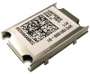
3: Mounting Instructions and PCB Footprint Figure 3-4 Hirose Connector Layout Product Information Label xPico Product Label Part Number Revision MAC Address Manufacturing Date Code Product Model Country of Origin Lantronix Datamatrix Barcode xPico® Embedded Device Server Integration Guide 37 - Lantronix xPico | xPico - Integration Guide - Page 38
3: Mounting Instructions and PCB Footprint Figure 3-6 xPico Wi-Fi Product Label Product Model Part Number Japan Certification Number Revision Number Canada Radio ID FCC Radio ID Japan Radio Equipment Mark Japan Telecommunication Mark Lantronix Datamatrix Barcode Manufacturing Date Code Serial - Lantronix xPico | xPico - Integration Guide - Page 39
xPico's reliability. For xPico Wi-Fi operation above +70° Celsuis, it is recommended that a heat pad be placed between the module ICC ICC ICC ICC ICC ICC ICC VRST RPU RPU VCP_IL Min 3.15 2.7 56 Typical 3.3 200 220 150 240 260 190 170 190 120 10 Max 3.46 2 122 0.8 VCP_IH 2 5.5 VCP_OL 0.4 - Lantronix xPico | xPico - Integration Guide - Page 40
4: Specifications Table 4-3 xPico WiFi Recommended Operating Conditions Parameter Symbol Min Typical Max 0.4 Vdc Vdc 0.8 Vdc Reset Pin High Voltage VRES_IL 2 Vcc+0.3 Vdc Note 1. For xPico Wi-Fi 5V tolerant pins, in order to sustain a voltage higher than Vcc+0.3, the internal pull- up - Lantronix xPico | xPico - Integration Guide - Page 41
web site at www.lantronix.com/support/warranty. Windows™ 98/NT/2000/XP-based Device Installer configuration software and Windows™-based Com Port Redirector See A:Compliance. Category CPU, Memory Firmware WLAN Standards Antenna Connector Frequency Band Table 4-5 xPico Wi-Fi Technical Specification - Lantronix xPico | xPico - Integration Guide - Page 42
4: Specifications Category Channel Support Modulation Protocols Supported Data Rates 802.11b Data Rates 802.11g Date Rates 802.11n 802.11b, CCK encryption Serves static Web pages and Java applets Storage capacity: TBD Kbytes 2.5 grams Metal shell xPico® Embedded Device Server Integration Guide 42 - Lantronix xPico | xPico - Integration Guide - Page 43
and mating PCB For details on the Lantronix warranty policy, go to our web site at www.lantronix.com/support/warranty. Windows™ 98/NT/2000/XP-based Device Installer configuration software and Windows™-based Com Port Redirector See A:Compliance. xPico® Embedded Device Server Integration Guide 43 - Lantronix xPico | xPico - Integration Guide - Page 44
Device Server) (According to ISO/IEC Guide 22 and EN 45014) Manufacturer's Name & Address: Lantronix, Inc. 167 Technology Drive, Irvine, CA 92618 USA Declares that the following product: Product Name Model: xPico® Embedded Device Server Conforms to the following standards or other normative - Lantronix xPico | xPico - Integration Guide - Page 45
B: Compliance (xPico Wi-Fi Embedded Device Server) (According to ISO/IEC Guide and EN 45014) Manufacturer's Name & Address: Lantronix, Inc. 167 Technology Drive, Irvine, CA 92618 USA Declares that the following product: Product Name Model: xPico® Wi-Fi® Embedded Device Server Conforms to the - Lantronix xPico | xPico - Integration Guide - Page 46
põhinõuetele ja nimetatud direktiivist tulenevatele teistele asjakohastele sätetele. Hereby, Lantronix, Inc., declares that this xPico Wi-Fi is in compliance with the essential requirements and other relevant provisions of Directive 1999/5/EC. xPico® Embedded Device Server Integration Guide 46 - Lantronix xPico | xPico - Integration Guide - Page 47
Lantronix, Inc xPico Wi-Fi 1999/5/ΕΚ. Français [French] Par la présente Lantronix, Inc. déclare que l'appareil xPico Wi-Fi Malti [Maltese] Hawnhekk, Lantronix, Inc.], jiddikjara li dan xPico Wi-Fi jikkonforma malħtiġijiet Swedish] Härmed intygar Lantronix, Inc. att denna xPico Wi-Fi står I ö - Lantronix xPico | xPico - Integration Guide - Page 48
not installed and used in accordance with the instructions, may cause harmful interference to radio communications is maintained between the antenna and users, and 2. The transmitter module may not be co-located with any other transmitter or antenna. xPico® Embedded Device Server Integration Guide 48 - Lantronix xPico | xPico - Integration Guide - Page 49
The grantee's FCC ID can be used only when all FCC compliance requirements are met. Manual Information To the End User The OEM integrator has to be aware not to provide information to compliance requirements required with this module installed. xPico® Embedded Device Server Integration Guide 49 - Lantronix xPico | xPico - Integration Guide - Page 50
"Contient des IC: 3867A-XPICOW". Manual Information To the End User The module in the user's manual of the end product which integrates this module. The end user manual shall include all required regulatory information/warning as show in this manual. xPico® Embedded Device Server Integration Guide - Lantronix xPico | xPico - Integration Guide - Page 51
on d'installer ou de supprimer ce module RF dans le manuel de l'utilisateur du produit final qui intègre ce module. Le manuel de l'utilisateur final more than that necessary for successful communication. This radio transmitter xPico Wi-Fi has been approved by Industry Canada to operate with the - Lantronix xPico | xPico - Integration Guide - Page 52
Fax: 949-453-3995 RoHS Notice All Lantronix products in the following families are China 0 0 0 WiPort 0 0 0 0 0 0 xDirect 0 0 0 0 0 0 xPico 0 0 0 0 0 0 xPico Wi-Fi 0 0 0 0 0 0 XPort 0 0 0 0 0 0 XPort Pro 0 xPico® Embedded Device Server Integration Guide 52
-
 1
1 -
 2
2 -
 3
3 -
 4
4 -
 5
5 -
 6
6 -
 7
7 -
8
-
9
-
10
-
11
-
12
-
13
-
14
-
15
-
16
-
17
-
18
-
19
-
20
-
21
-
22
-
23
-
24
-
25
-
26
-
27
-
28
-
29
-
30
-
31
-
32
-
33
-
34
-
35
-
36
-
37
-
38
-
39
-
40
-
41
-
42
-
43
-
44
-
45
-
46
-
47
-
48
-
49
-
50
-
51
-
52
 |
 |

xPico
Embedded Device Server
Integration Guide
Part Number 900-619
Revision G
February 2014