Lantronix xPico xPico - Integration Guide - Page 24
xPico Signal, DCE Connector, xPico, Signal, logic, Description, RS485, Serial Port Example
 |
View all Lantronix xPico manuals
Add to My Manuals
Save this manual to your list of manuals |
Page 24 highlights
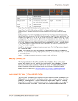
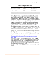
Figure 2-8 Serial Port Example 2: Functional Description Table 2-9 RS232 Connections (Serial Transceiver Required) xPico Signal Signal Description (Logic) RXDx Data In TXDx Data Out RTSx H/W Flow Control Output CTSx H/W Flow Control Input CPx Modem Control Input CPy Modem Control Output DCE Connector DB9 DB25 Signal 2 3 3 2 7 4 8 5 1 8 4 20 RXDx TXDx RTSx CTSx DCDx DTRx DTE Connector DB9 DB25 3 2 2 3 8 5 7 4 4 20 1 8 Signal TXDx RXDx CTSx RTSx DTRx DCDx xPico Signal (logic) TXDx TXDx RXDx RXDx RTSx CPx CPy Table 2-10 RS422/485 Connections (Serial Transceiver Required) Description RS485 Signal DB25 4 DB25 2 DB9 4 Wire Wire wire DB9 2 wire Data Out TX+485 14 14 7 7 Data Out TX-485 15 15 3 3 Data In RX+485 21 14 2 7 Data In RX-485 22 15 8 3 TX Enable RS485 Select RS485 2-wire Note: The IO pins for xPico Wi-Fi are set to floating input on power up until configured by unit firmware. An external 100K ohm pull-up may be required on the serial transmit signal to prevent downstream UART devices from detecting false characters on initial power up. xPico® Embedded Device Server Integration Guide 24
-
 1
1 -
2
-
3
-
4
-
5
-
6
-
7
-
8
-
9
-
10
-
11
-
12
-
13
-
14
-
15
-
16
-
17
-
18
-
 19
19 -
 20
20 -
 21
21 -
 22
22 -
 23
23 -
 24
24 -
 25
25 -
 26
26 -
 27
27 -
 28
28 -
 29
29 -
30
-
31
-
32
-
33
-
34
-
35
-
36
-
37
-
38
-
39
-
40
-
41
-
42
-
43
-
44
-
45
-
46
-
47
-
48
-
49
-
50
-
51
-
52
 |
 |
