Lantronix xPico xPico - Integration Guide - Page 16
Signal Name, xPico, Primary Function, Reset, State, Internal, Pull-up, Driver, Strength, Table 2-3
 |
View all Lantronix xPico manuals
Add to My Manuals
Save this manual to your list of manuals |
Page 16 highlights
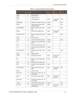
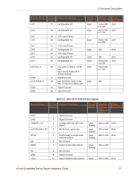
2: Functional Description Table 2-3 xPico (wired) PCB Interface Signals Signal Name GND GND CP8 xPico Pin # 1 2 3 Primary Function Signal Ground Signal Ground Configurable I/O Reset State Input LED1/LINK RTS1 LED0/SPEED RXD1 4 Ethernet Link LED, active low Output 5 Serial ready to send/ serial Output transmit enable 6 Ethernet speed LED, active Output low 7 Serial receive data input 1 Input LED2/ACTIVITY 8 Ethernet Activity LED, active Output low GND 9 Signal Ground TXD1 10 Serial transmit data output 1 Output TX- 11 Ethernet transmit differential Output (neg) TCT 12 Ethernet transmit center tap TX+ 13 Ethernet transmit differential Output (pos) LED3/DUPLEX 14 Ethernet Duplex LED, active Output low GND 15 Signal Ground CTS1 16 Serial Clear to Send Input RXRCT RX+ SYSTEM_LED GND Reserved RXD2 17 Ethernet receive differential Input (neg) 18 Ethernet receive center tap 19 Ethernet receive differential Input (pos) 20 System status LED, active high Input 21 Signal Ground 22 Reserved for future use. Do not connect. 23 Serial receive data input 2 Input Reserved TXD2 CP2/INT 24 Reserved for future use. Do not connect. 25 Serial transmit data output 2 Output 26 Configurable I/O-External interrupt input Input Internal Pull-up Driver Strength Active 56K to 122K 4mA 8mA 2mA 8mA Active 56K to 122K 8mA 2mA 8mA Active 56K to 122K Active 56K 4mA to 122K Active 56K to 122K Active 56K to 122K 2mA 4mA xPico® Embedded Device Server Integration Guide 16
-
 1
1 -
2
-
3
-
4
-
5
-
6
-
7
-
8
-
9
-
10
-
 11
11 -
 12
12 -
 13
13 -
 14
14 -
 15
15 -
 16
16 -
 17
17 -
 18
18 -
 19
19 -
 20
20 -
 21
21 -
22
-
23
-
24
-
25
-
26
-
27
-
28
-
29
-
30
-
31
-
32
-
33
-
34
-
35
-
36
-
37
-
38
-
39
-
40
-
41
-
42
-
43
-
44
-
45
-
46
-
47
-
48
-
49
-
50
-
51
-
52
 |
 |
