Lantronix xPico xPico - Integration Guide - Page 22
How to Connect a Lantronix Embedded Module to a, Wired Ethernet Port, Manufacturer, Part Number
 |
View all Lantronix xPico manuals
Add to My Manuals
Save this manual to your list of manuals |
Page 22 highlights
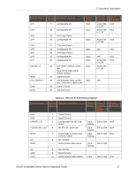
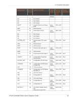
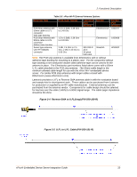
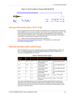
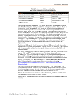
2: Functional Description Table 2-7 Recommended Magnetic Modules and Combo RJ45/Magnetic Module Connectors Type Magnetic only (requires RJ45) Magnetic only (requires RJ45) Combination RJ45/Magnetic Combination RJ45/Magnetic Magnetic for POE Manufacturer BI-Tech Mingtek Belfuse Midcom PULSE Part Number HS91-011-80LFTR HN0013SG 08B0-1D1T-06-F MIC2411D-0117T-LF3 HX2019 The Ethernet differential pair signals, ERX-/ERX+ and ETX-/ETX+ should be routed as 100-ohm differential pairs on a layer next to the signal ground plane. The use of vias on these signals should be minimized. The center tap signal connections between the magnetic and xPico (wired) module are required. Center tap signals RCT and TCT should be routed with at least 20 mil trace thickness. The area between the magnetic module and RJ45 jack, including the area under both, should be voided of all signals and planes, except for the signals connecting to both. The signals connecting between the RJ45 and magnetic are required to be isolated by 1500Vrms from all other signals and planes, including chassis and signal ground. The connector shield should be connected to chassis. It is recommended that 1206 resistor pads from chassis ground to signal ground be placed next to each of the shield tabs. The resistor pads allow for 0 ohm jumper, ferrite beads, or decoupling caps to be installed as needed for EMI/EMC improvement. The Ethernet LED signals should be routed to discrete LEDs or to the LED pins on the RJ45 through 220 ohm or larger resistors. The LED signals are active low. The Ethernet LED signals should be isolated from the signals that connect between the RJ45 and magnetic module. Also shown in the reference schematic is a recommended TVS array that can be used to improve ESD and EFT in harsh environments. The device shown is Semtec RCIamp0502A. This device features route through pin assignments allowing for the Ethernet differential signal pairs to be routed without altering the trace impedance or adding vias. Due to this routing, the device could be installed or depopulated as needed. See the Lantronix app note, How to Connect a Lantronix Embedded Module to a Wired Ethernet Port for more details on Ethernet connection and routing, http://www.lantronix.com/pdf/appnotes/Connect-LTRX-Embed-Module-to-WiredEthernet_AN.pdf. The xPico module can also be powered from POE using a POE magnetic and POE powered device controller. Lantronix uses the Silabs, Si3402 POE controller to power the xPico development board via POE. If using POE the Ethernet magnetic module should be changed to a POE compatible module such as Pulse HX2019. Refer to the evaluation board schematic in the xPico-DevKit_UG for an example circuit. http://www.lantronix.com/pdf/xPico-DevKit_UG.pdf. Refer to the SiLabs data sheet for Si3402 for more information on using the SiLabs POE controller. xPico® Embedded Device Server Integration Guide 22
-
 1
1 -
2
-
3
-
4
-
5
-
6
-
7
-
8
-
9
-
10
-
11
-
12
-
13
-
14
-
15
-
16
-
 17
17 -
 18
18 -
 19
19 -
 20
20 -
 21
21 -
 22
22 -
 23
23 -
 24
24 -
 25
25 -
 26
26 -
 27
27 -
28
-
29
-
30
-
31
-
32
-
33
-
34
-
35
-
36
-
37
-
38
-
39
-
40
-
41
-
42
-
43
-
44
-
45
-
46
-
47
-
48
-
49
-
50
-
51
-
52
 |
 |
