Lantronix xPico xPico - Integration Guide - Page 15
PCB Interface, xPico Wired
 |
View all Lantronix xPico manuals
Add to My Manuals
Save this manual to your list of manuals |
Page 15 highlights
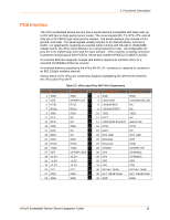
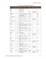
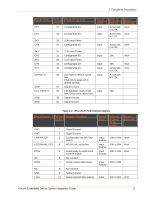
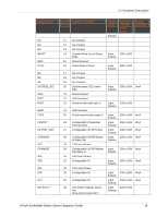
2: Functional Description PCB Interface The xPico embedded device servers has a serial interface compatible with data rates up to 921,600 bps (in high-performance mode). The serial signals (RX, TX, RTS, CTS, and all CPs) are 3.3V CMOS logic level and 5V tolerant. The serial interface pins include +3.3V, ground, and reset. The serial signals usually connect to an internal device, such as a UART. For applications requiring an external cable running with RS-232 or RS422/485 voltage levels, the xPico must interface to a serial transceiver chip. All configurable I/O pins are 3.3V CMOS logic level and 5V input tolerant. xPico requires a mating connector. Customers should layout their PCB for Hirose part number DF40C(2.0)-40DS-0.4V(51). An external Ethernet magnetic module and RJ45 is required to interface xPico to a standard 10/100Mbps Ethernet network. An external antenna attached to the xPico Wi-Fi U.FL connector is required to connect to an 802.11b/g/n wireless network. Shown below is the xPico pin connection diagram highlighting the differences between the xPico and xPico Wi-Fi. Table 2-2 xPico and xPico Wi-Fi Pin Connections Pin# xPico Wired 1 GND 3 CP8 5 RTS1 7 RXD1 9 GND 11 ETX13 ETX+ 15 GND 17 ERX19 ERX+ 21 GND 23 RXD2 25 TXD2 27 CP7 29 +3.3V 31 +3.3V 33 +3.3V 35 CP1 37 GND 39 GND xPico Wi-Fi GND CP8/SPI_CS RTS1 RXD1 GND NC NC GND NC NC GND RXD2 TXD2 CP7/SPI_SCK +3.3V +3.3V +3.3V CP1 GND GND Pin# xPico Wired 2 GND 4 LED1/LINK 6 LED0/SPEED 8 LED2/ACTIVITY 10 TXD1 12 ETCT 14 LED3/DUPLEX(OUT) 16 CTS1 18 ERCT 20 SYS_LED 22 Reserved 24 Reserved 26 CP2/INT 28 CP3 30 CP4 32 CP5 34 CP6 36 DEFAULT#(IN) 38 EXT_RESET#(IN) 40 GND xPico Wi-Fi GND LED1/WLAN_LED NC NC TXD1 NC WKUP (IN) CTS1 NC SYS_LED DDP DDM CP2/SPI_INT CP3/MISO CP4/MOSI CP5 CP6 DEFAULT#(IN) EXT_RESET#(IN) GND xPico® Embedded Device Server Integration Guide 15
-
 1
1 -
2
-
3
-
4
-
5
-
6
-
7
-
8
-
9
-
 10
10 -
 11
11 -
 12
12 -
 13
13 -
 14
14 -
 15
15 -
 16
16 -
 17
17 -
 18
18 -
 19
19 -
 20
20 -
21
-
22
-
23
-
24
-
25
-
26
-
27
-
28
-
29
-
30
-
31
-
32
-
33
-
34
-
35
-
36
-
37
-
38
-
39
-
40
-
41
-
42
-
43
-
44
-
45
-
46
-
47
-
48
-
49
-
50
-
51
-
52
 |
 |
