Lantronix xPico xPico - Integration Guide - Page 18
Configurable I/O/SPI Master
 |
View all Lantronix xPico manuals
Add to My Manuals
Save this manual to your list of manuals |
Page 18 highlights
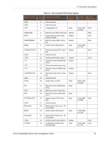
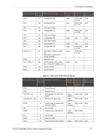
2: Functional Description Signal Name NC NC NC WKUP4 GND CTS17 NC NC NC SYSTEM_LED GND DDP2 RXD2 DDM2 TXD2 CP2/INT1 CP7/SPI_SCK1 CP3/MISO1 3V3 CP4/MOSI1 3V3 CP5 3V3 CP6 CP1 DEFAULT# xPico Pin # 11 12 13 14 15 16 17 18 19 20 21 22 23 24 25 26 27 28 29 30 31 32 33 34 35 36 Primary Function No Connect No Connect No Connect System Wake Up on Rising Edge Signal Ground Serial Clear to Send No Connect No Connect No Connect System status LED, active high Signal Ground USB (positive) Serial receive data input 2 USB Negative Serial transmit data output 2 Configurable I/O-External interrupt input Configurable I/O/ SPI Clock Configurable I/O/SPI Master In-Slave Out 3.3V Input Power Configurable I/O/ SPI Master Out-Slave In 3.3V Input Power Configurable I/O 3.3V Input Power Configurable I/O Configurable I/O Unit reset to default, active low. Drive low to reset unit to Reset State floating Input, floating Input, floating Input, floating Input, floating Input, floating Input, floating Input, floating Input, floating Input, floating Input, floating Input, floating Input, floating Input, floating Internal Pull-up /Pulldown Driver Strength 30K to 50K 30K to 50K 30K to 50K 8mA 30K to 50K 30K to 50K 8mA 30K to 50K 8mA 30K to 50K 8mA 30K to 50K 8mA 30K to 50K 8mA 30K to 50K 8mA 30K to 50K 8mA 30K to 50K 8mA 30K to 50K xPico® Embedded Device Server Integration Guide 18
-
 1
1 -
2
-
3
-
4
-
5
-
6
-
7
-
8
-
9
-
10
-
11
-
12
-
 13
13 -
 14
14 -
 15
15 -
 16
16 -
 17
17 -
 18
18 -
 19
19 -
 20
20 -
 21
21 -
 22
22 -
 23
23 -
24
-
25
-
26
-
27
-
28
-
29
-
30
-
31
-
32
-
33
-
34
-
35
-
36
-
37
-
38
-
39
-
40
-
41
-
42
-
43
-
44
-
45
-
46
-
47
-
48
-
49
-
50
-
51
-
52
 |
 |
