Lantronix xPico xPico - Integration Guide - Page 40
Parameter, Symbol, Typical, Units, Table 4-3, xPico WiFi Recommended Operating Conditions
 |
View all Lantronix xPico manuals
Add to My Manuals
Save this manual to your list of manuals |
Page 40 highlights
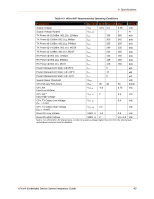
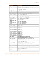
4: Specifications Table 4-3 xPico WiFi Recommended Operating Conditions Parameter Symbol Min Typical Max Units Supply Voltage Supply Voltage Ripples TX Power @ 16.5dBm, 802.11b, 11Mbps TX Power @ 15dBm, 802.11g, 6Mbps TX Power @ 13dBm, 802.11g, 54Mbps TX Power @ 14.5dBm, 802.11n, MCS0 TX Power @ 12dBm, 802.11n, MCS7 RX Power @ 802.11b, 11Mbps RX Power @ 802.11g, 54Mbps RX Power @ 802.11n, MCS7 Power Management State 1 @ 25°C Power Management State 1 @ +85°C Power Management State 1 @ -40°C Supply Reset Threshold CPx Pull-ups/ Pull-downs CPx, RX Input Low Voltage CPx, RX(1) Input High Voltage VCC VCC_PP ICC ICC ICC ICC ICC ICC ICC ICC ICC ICC ICC VRST RPU VCP_IL VCP_IH 3.15 3.3 330 300 255 290 230 125 125 125 6 12 5 30 40 -0.3 2 3.46 Vdc 2 % 380 mA 345 mA 295 mA 335 mA 265 mA 150 mA 150 mA 150 mA μA μA μA Vdc 50 Kohm 0.75 Vdc 5.5 Vdc CPx, TX Output Low Voltage (IOL = 4 mA) CPx, TX Output High Voltage (IOH = -4 mA) Reset Pin Low Voltage VCP_OL VCP_OH 2.4 VRES_IL -0.3 0.4 Vdc Vdc 0.8 Vdc Reset Pin High Voltage VRES_IL 2 Vcc+0.3 Vdc Note 1. For xPico Wi-Fi 5V tolerant pins, in order to sustain a voltage higher than Vcc+0.3, the internal pull- up/pull-down resistors must be disabled. xPico® Embedded Device Server Integration Guide 40
-
 1
1 -
2
-
3
-
4
-
5
-
6
-
7
-
8
-
9
-
10
-
11
-
12
-
13
-
14
-
15
-
16
-
17
-
18
-
19
-
20
-
21
-
22
-
23
-
24
-
25
-
26
-
27
-
28
-
29
-
30
-
31
-
32
-
33
-
34
-
 35
35 -
 36
36 -
 37
37 -
 38
38 -
 39
39 -
 40
40 -
 41
41 -
 42
42 -
 43
43 -
 44
44 -
 45
45 -
46
-
47
-
48
-
49
-
50
-
51
-
52
 |
 |
