Lantronix xPico xPico - Integration Guide - Page 35
Aligning Mounting Clip Legs to Standoff Holes
 |
View all Lantronix xPico manuals
Add to My Manuals
Save this manual to your list of manuals |
Page 35 highlights
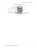
3: Mounting Instructions and PCB Footprint Figure 3-2 Aligning Mounting Clip Legs to Standoff Holes 6. Insert the white clip legs furthest from the J1 connector first and gently push down on the xPico module above the J1 connector. Keep the module as level as possible during installation. Note: When removing the xPico embedded device server from the evaluation board, gently tug the module. Do not use excessive force or attempt to remove the xPico module by grasping and pulling the module from the short end opposite the module connector as this may cause damage to the J1 evaluation board connector. xPico® Embedded Device Server Integration Guide 35
-
 1
1 -
2
-
3
-
4
-
5
-
6
-
7
-
8
-
9
-
10
-
11
-
12
-
13
-
14
-
15
-
16
-
17
-
18
-
19
-
20
-
21
-
22
-
23
-
24
-
25
-
26
-
27
-
28
-
29
-
 30
30 -
 31
31 -
 32
32 -
 33
33 -
 34
34 -
 35
35 -
 36
36 -
 37
37 -
 38
38 -
 39
39 -
 40
40 -
41
-
42
-
43
-
44
-
45
-
46
-
47
-
48
-
49
-
50
-
51
-
52
 |
 |

3: Mounting Instructions and PCB Footprint
Figure 3-2
Aligning Mounting Clip Legs to Standoff Holes
6.
Insert the white clip legs furthest from the J1 connector first and gently push down on
the xPico module above the J1 connector.
Keep the module as level as possible
during installation.
Note:
When removing the xPico embedded device server from the evaluation
board, gently tug the module.
Do not use excessive force or attempt to remove
the xPico module by grasping and pulling the module from the short end opposite
the module connector as this may cause damage to the J1 evaluation board
connector.
xPico® Embedded Device Server Integration Guide
35