Lantronix xPico xPico - Integration Guide - Page 19
Mating Connector, Antenna Interface (xPico Wi-Fi Only), DF40C 2.0-40DS-0.4V 51.
 |
View all Lantronix xPico manuals
Add to My Manuals
Save this manual to your list of manuals |
Page 19 highlights
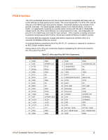
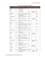
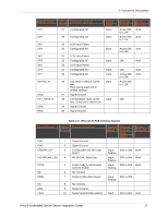
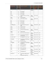
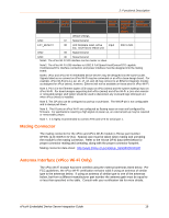
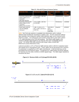
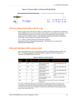
2: Functional Description Signal Name xPico Primary Function Pin # Reset State Internal Pull-up /Pulldown Driver Strength default settings. GND 37 Signal Ground EXT_RESET# 38 Unit hardware reset, active Input low. Drive low to reboot unit. 30K to 50K GND 39 Signal Ground GND 40 Signal Ground Note1: The xPico Wi-Fi SPI interface can be master or slave. Note2: The xPico Wi-Fi USB interface is USB2.0 Full Speed Host/Device/OTG capable. Host/Device/OTG interface connectors and power interface must be designed into the mating board. Note3. xPico and xPico Wi-Fi embedded device servers may be designed into the same socket. Signals listed as no connect on xPico Wi-Fi may be connected on an xPico base design board. For example, xPico Wi-Fi pins 11, 12, 13, 17, 18, and 19 may connect to an Ethernet magnetic module as designed for xPico (wired), however, Ethernet will not be available on those pins for xPico Wi-Fi. Note 4. Pin 14 is the Ethernet duplex LED output on xPico (wired) and the system wakeup input on xPico Wi-Fi. For board designs supporting both xPico (wired) and xPico Wi-Fi, a zero ohm resistor or removable jumper stuff option should be used to disconnect any on-board logic driving pin 14 when xPico (wired) is installed. Note 5. The CP pins can be configured as pull-up or pull-down. The WKUP pin is not configurable and is always pull-down. Note 6. The IO pins on xPico Wi-Fi are configured as floating-input on reset until configured by firmware. For applications requiring a high signal on power up, an external pull-up may be required or removeable jumper. Note 7. It is highly recommended to connect RTS and CTS for serial port 1. Mating Connector The mating connector for the xPico and xPico Wi-Fi module is Hirose part number DF40C (2.0)-40DS-0.4V (51). Special care must be taken when mating and unmating the module to the mating connector. Refer to the Hirose DF40 data sheet below for proper connector mating and unmating, along with the proper connector footprint. Mating connector data sheet: http://www.hirose.co.jp/cataloge_hp/e68440018.pdf Antenna Interface (xPico Wi-Fi Only) The xPico Wi-Fi module has been certified using the external antennas listed below. Per FCC guidelines, the xPico Wi-Fi certification remains valid if using an antenna of similar type to the antennas below. If using an antenna of similar type to one of the antennas below, but from a different manufacturer part number the antenna gain must be equal to or less than specified in the table. Consult with your certification lab for more details. xPico® Embedded Device Server Integration Guide 19
-
 1
1 -
2
-
3
-
4
-
5
-
6
-
7
-
8
-
9
-
10
-
11
-
12
-
13
-
 14
14 -
 15
15 -
 16
16 -
 17
17 -
 18
18 -
 19
19 -
 20
20 -
 21
21 -
 22
22 -
 23
23 -
 24
24 -
25
-
26
-
27
-
28
-
29
-
30
-
31
-
32
-
33
-
34
-
35
-
36
-
37
-
38
-
39
-
40
-
41
-
42
-
43
-
44
-
45
-
46
-
47
-
48
-
49
-
50
-
51
-
52
 |
 |