Lantronix xPico xPico - Integration Guide - Page 25
USB Device Port (xPico Wi-Fi only), Pin Name, Description, Connector, Signal, Requirement, Mini Type B
 |
View all Lantronix xPico manuals
Add to My Manuals
Save this manual to your list of manuals |
Page 25 highlights
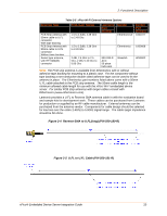
2: Functional Description USB Device Port (xPico Wi-Fi only) The xPico Wi-Fi embedded device server has one USB2.0 Full Speed Device port interfaces for connection to an upstream USB device. The port consists of a differential pair, signals DDP and DDM. These signals should be routed as a 90 ohm differential pair on a signal layer next to the signal ground plane. The use of vias should be minimized on these signals. The USB signals can be connected to a USB Mini Type B USB port (as shown in Table 2-12) directly to an IC with a USB host port. If connecting to an external port that is user accessible it is recommended to add a TVS diode array to the signal nets for ESD protection. The ESD array shown in the figure is of type Semtech RCIamp0502A. This device features through pin routing to minimize trace impedance changes and simplify routing. The footprint for the TVS array can be added to the PCB and the part can be depopulated if it is not needed. It is recommended that the power drawn off the USB Mini Type B connector be limited to less than 500mA per USB requirements. If the USB device port is unused the DDP and DDM pins may be left unconnected. Table 2-11 USB Host Port Signals Pin Name Description DDP DDM 5V Ground USB Device Port Positive pin USB Device Port Negative pin 5V power from USB cable Signal Ground Connector Pins 22 24 Ground Signal Requirement Route as 90 ohm differential pair with DDM signal Route as 90 ohm differential pair with DDP signal Current limit to 500 mA per port Ground plane Mini Type B USB Device connector pin 3 2 1 5 Figure 2-9 USB Device Interface Example (xPico Wi-Fi only) xPico® Embedded Device Server Integration Guide 25
-
 1
1 -
2
-
3
-
4
-
5
-
6
-
7
-
8
-
9
-
10
-
11
-
12
-
13
-
14
-
15
-
16
-
17
-
18
-
19
-
 20
20 -
 21
21 -
 22
22 -
 23
23 -
 24
24 -
 25
25 -
 26
26 -
 27
27 -
 28
28 -
 29
29 -
 30
30 -
31
-
32
-
33
-
34
-
35
-
36
-
37
-
38
-
39
-
40
-
41
-
42
-
43
-
44
-
45
-
46
-
47
-
48
-
49
-
50
-
51
-
52
 |
 |
